This is the final blog post in a series on converting a 1978 Puch Maxi Moped from fuel combustion, to electric powered.
Read Part 1 here. Read Part 2 here. Read Part 3 here. Read Part 4 here. Read Part 5 here.
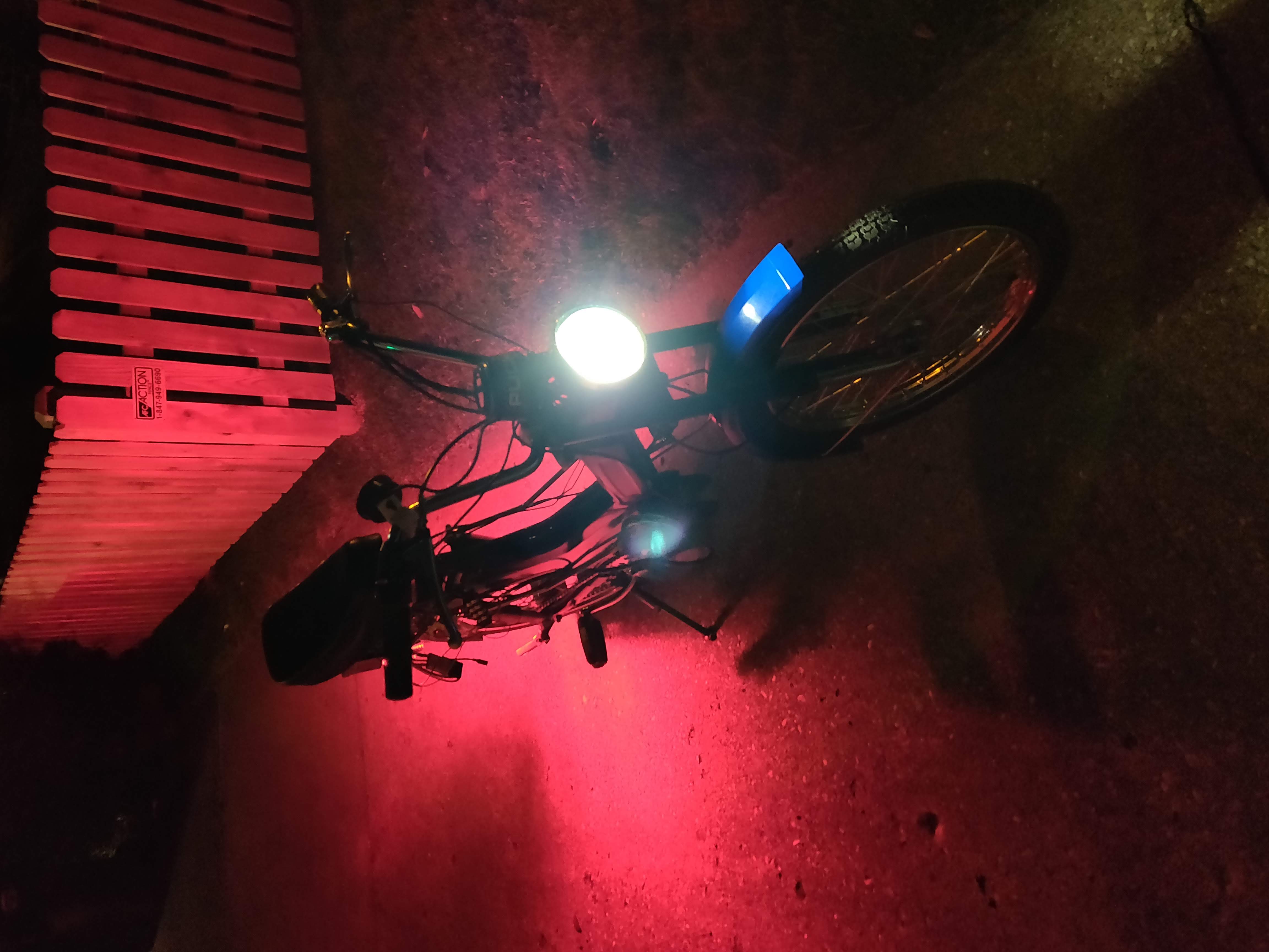
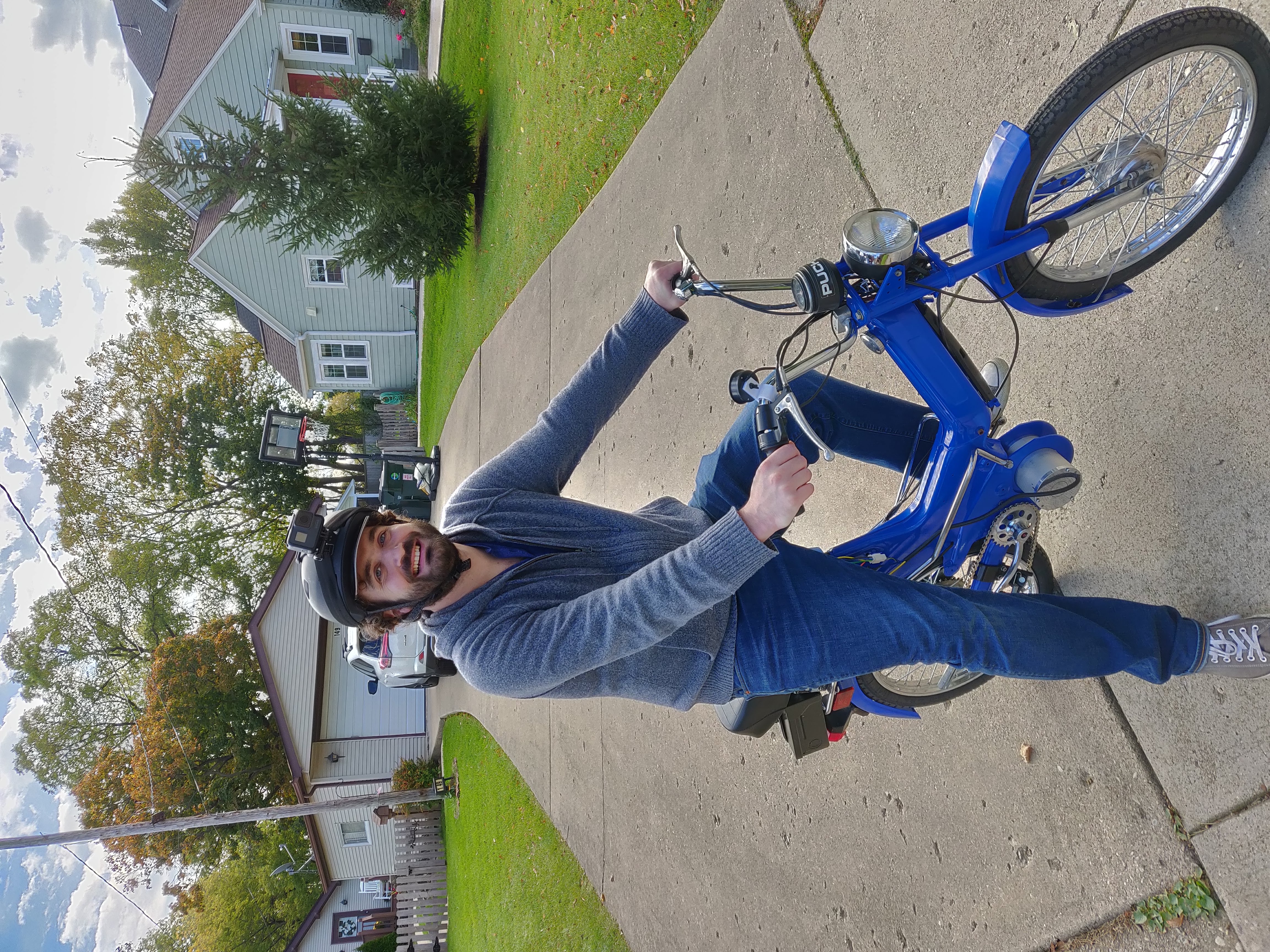
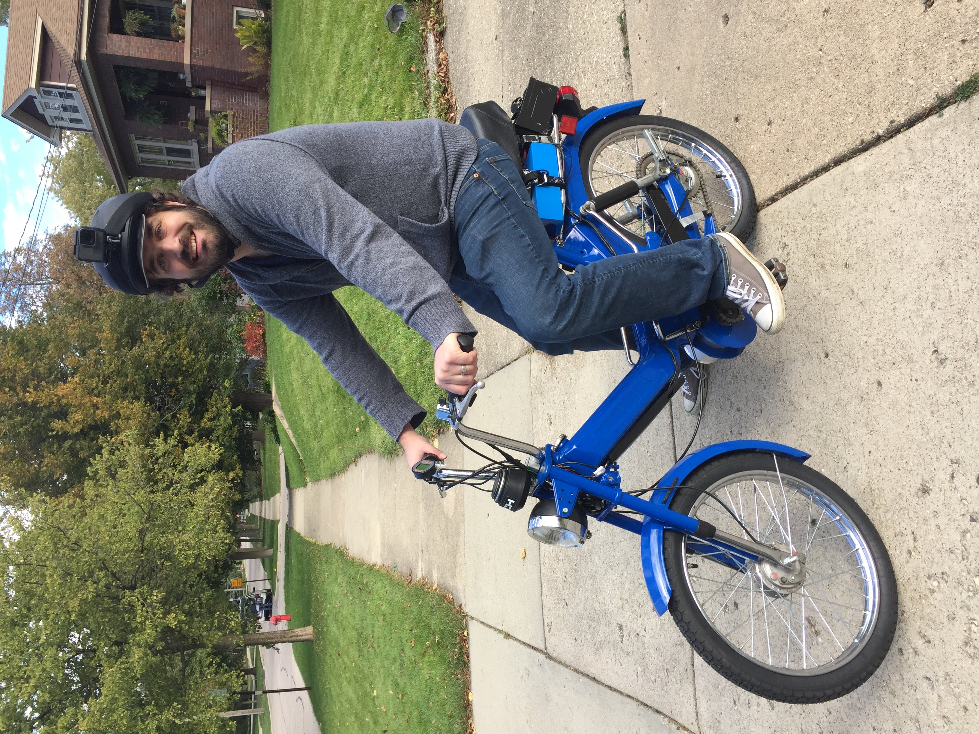
Today, I took the moped for it’s first successful test drive!
Look at her go! We’re affectionately naming her “The Blueberry Rocket”.
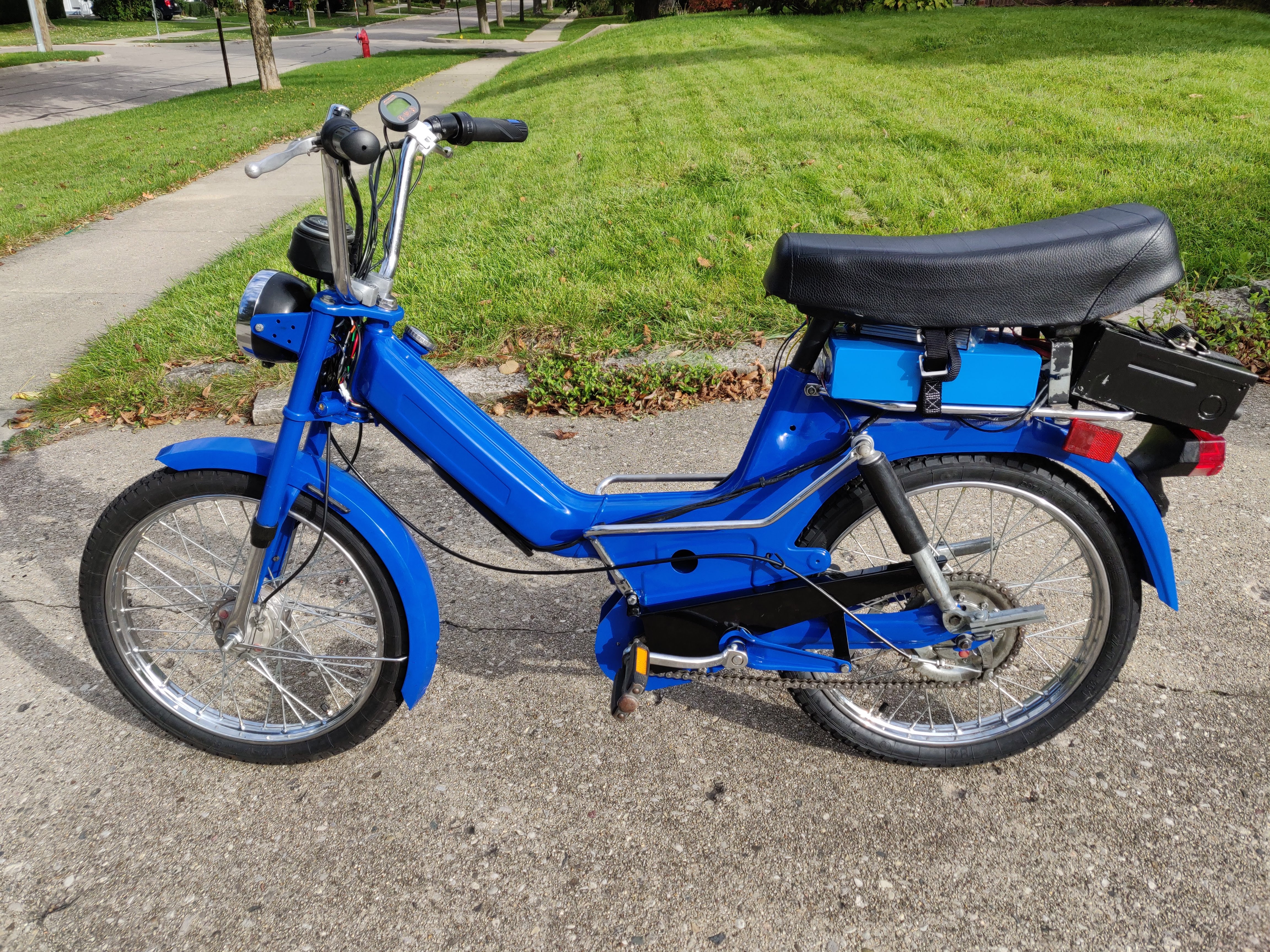

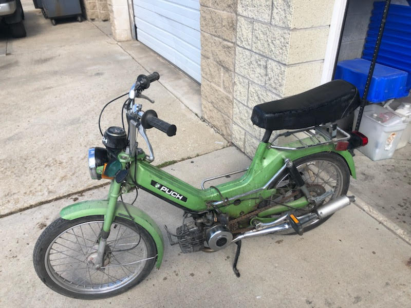
It’s hard to believe that it looked like this just 5 months ago:
I’ll share a few final details of the build, for those who might want to follow along. I plan on doing one more less technical post for those that might be interested in reading about the build from a high level.
Final Wiring
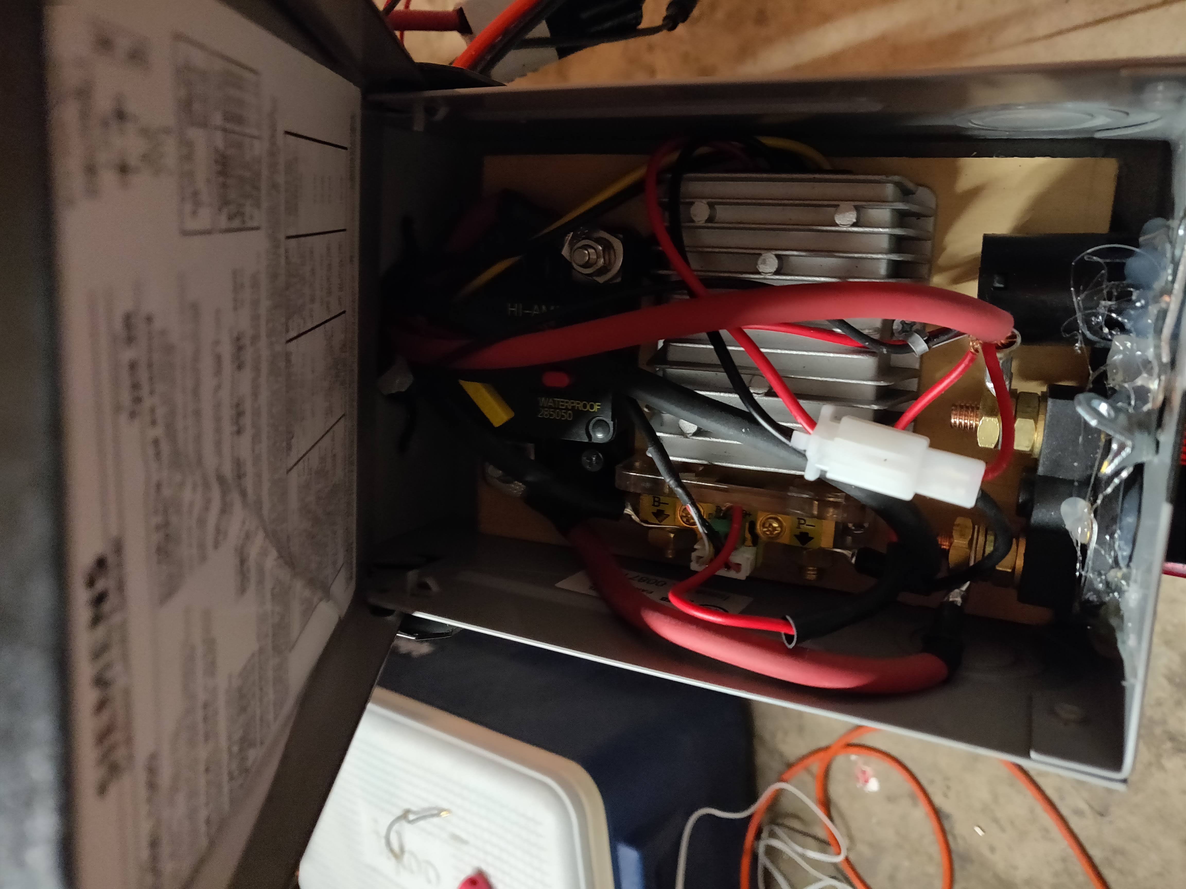
The last step was to complete the final motor circuit for the 48V electrical system. This means connecting all the different electrical components (circuit breaker, shunt, battery disconnect, 48 to 12v DC converter) together in the black electrical box.
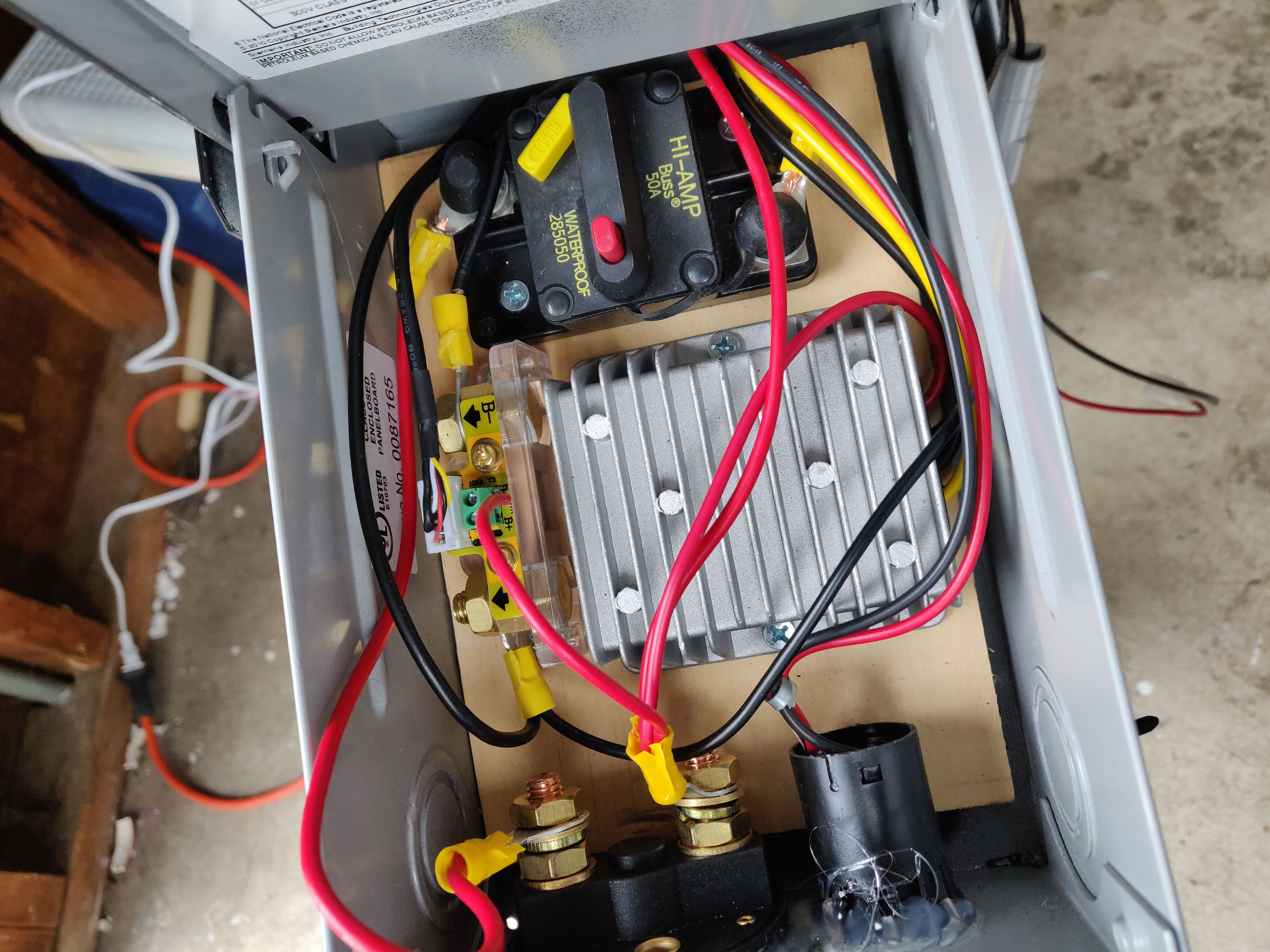
I used some nice hydraulic crimpers to make the mating Anderson cables that connected to the battery. After connecting this all together, the motor turned, and the shunt lit up!
Only two problems:
- After some consideration, I realized that the 14 gauge cable I used was too thin gauge to push the 30+ Amps necessary to drive the motor.
- The motor was spinning in the wrong direction.
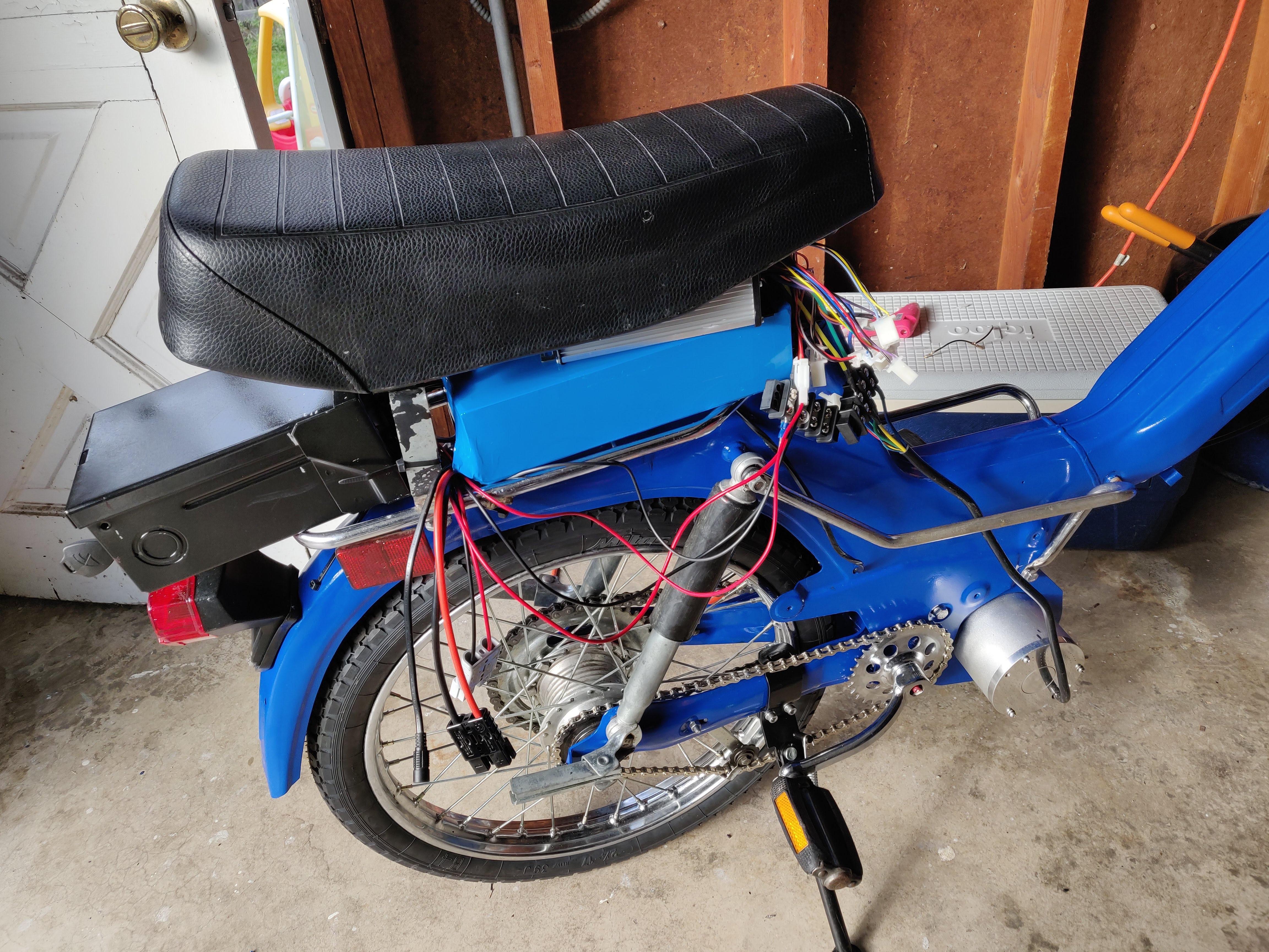
I recabled the circuit with 8 gauge wire, using the hydraulic crimpers to add ring connectors. I originally didn’t want to spend the money on the hydraulic crimpers, but it was so worth it, especially to make solid connections on this thicker gauge cable.
I toggled the “reverse connector” on the motor controller to make the wheel spin the other way, which presented another problem: The wheel was spinning in reverse, but was going really slow.
Turns out, that “reverse connector” on the motor controller also makes the wheel spin much slower. I needed to switch the rotation of the motor by switching the phase of motor power cables, as well as switching the hall sensor cables around. Configuration 2 from this forum post worked like a charm for me:
Standard Phase wire configuration:
U = Yellow V = Green W = Blue
…With the Green and Yellow Hall sensor wires transposed, transpose the phase wires:
Blue and Yellow Phase wires transposed (This is the working combination for the 10kW BLDC motor with the Green and Yellow Hall sensor wires transposed) U = Blue V = Green W = Yellow
After that, it ran at high speed just great!
Wrapping it Up
There are some other odds and ends that I’ll slowly work on: Cleaning up and hiding the cabling better, protecting the battery and electrical systems from the elements better, getting a custom decal made for the frame, getting the brakes to be more responsive. It’s fall here in Chicago, so I’m going to slow-burn some of this final work over the winter to be ready to really ride in the spring.
It’s still hard to believe that it works! This has been 5 months of continuously solving problems and clearing roadblocks. It’s been a really fun challenge, and is a joy to ride. I set out to learn about how EVs work, and I definitely accomplished that. I was able to restore a beautiful bike and make it totally zero emissions in the process.
Who knows? Maybe next it’s time to get a solar panel to charge the thing. :-)