UPDATE: Click here for part 2.
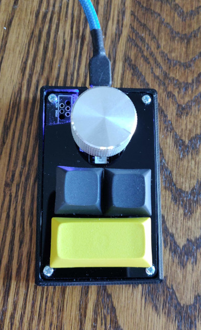
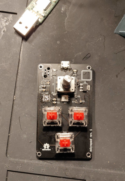
I recently completed the first revision prototype of a USB media controller keyboard “macropad”. I’m not a fan of the touchbar based media control buttons on my work MacBook Pro, and wanted a way to control my music and audio volume (especially for video calls) with big chunky, tactile buttons instead.
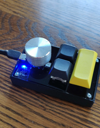
The result is an Open Source Hardware USB Keyboard I call micropad.
Its specifications include:
- A custom circuit and PCB designed in KiCAD.
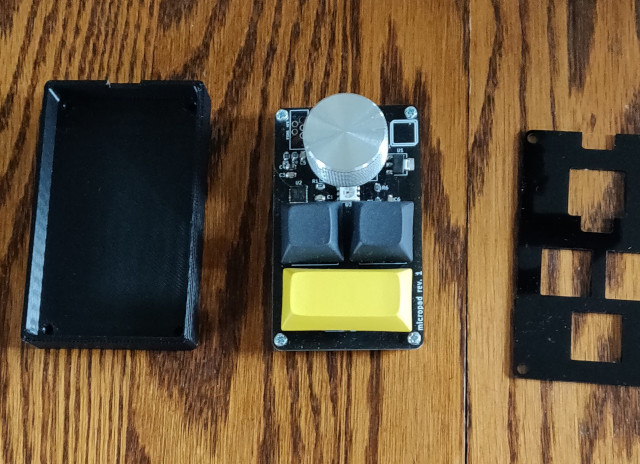
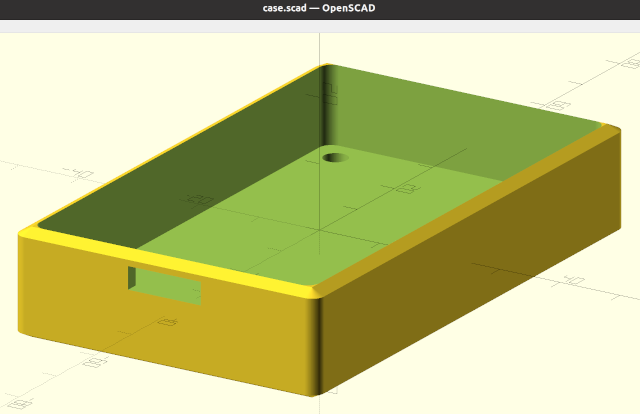
- A custom keyboard case and top plate designed in OpenSCAD.
- Custom firmware, written in Rust for an STM32F042 microcontroller.
- A command line USB-CDC command line client to control the device via a serial port protocol while the device is plugged into the host computer.
- A chunky rotary encoder knob, for volume control. Forward, Backward, Play / Pause buttons to control media (mostly Spotify).
Hardware Design
While I’ve built my own full-sized USB keyboard before, I wanted to try a few new things hardware wise with this project.
- USB-C: I’ve done plenty of USB Micro projects, but I wanted to support a USB-C connector for power and data for this project.
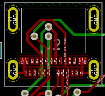
- Replace the standard 10-pin 1.27mm pitch JTAG pin header I use on most projects with something that requires no additional pin header for firmware programming. I settled on these SKEDD connector cables that I really like. Check out the adapter board on GitHub.
- Experiment with ENIG, gold plated PCB finish, and black PCB solder-mask.
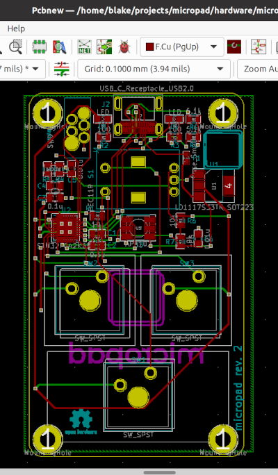
Many of the other existing hardware design ideas were remixes of existing projects I’ve had success with in the past. I improved the rotary encoder accuracy by actually including a rotary encoder filter circuit into the schematic. I used standard Cherry MX keyboard switches I had laying around from a previous project for the media control buttons, but was able to skip the scan matrix that is normally required when you have more input buttons than microcontroller pins.
The most difficult part of the hardware design has been getting the PCB and case design to fit correctly. I still haven’t found a good workflow to connect OpenSCAD and KiCAD so I can get exact / precise alignment with mounting holes and components tolerances. As much as I appreciate the “CAD as source code” nature of OpenSCAD, getting good component fits will probably push me to try something different like FreeCAD with my next hardware design project.
Firmware
Before this project, I built a small proof of concept board that used Rust and an ATSAMD51, so I was pretty confident I could get Rust going on an STM32F042, and make its USB hardware peripheral work with Rust. My previous keyboard’s firmware was written in C++, and I wanted to see if I could mimic a lot of that existing functionality in Rust.
I was able to leverage some really spectacular Rust crates, that made this project so much simpler and more intuitive than working in C++. I spent weeks in the past getting USB to work with crappy STM32 vendor examples that I could scour on the internet. Even after getting this C++ implementation to work, so much of that USB handling code wasn’t portable to other microcontrollers.
Instead, on this project, I used the usb-device crate, which provides an easy abstraction over common USB firmware implementations, including USB handshake handling, device descriptors, and communications polling.
unsafe {
    let bus_allocator = {
        USB_BUS_ALLOC = Some(UsbBus::new(usb));
        USB_BUS_ALLOC.as_ref().unwrap()
    };
    *USB_KEYBOARD.borrow(cs).borrow_mut() = Some(KeyboardHidClass::new(&bus_allocator));
    *USB_SERIAL.borrow(cs).borrow_mut() = Some(SerialPort::new(&bus_allocator));
    *USB_DEV.borrow(cs).borrow_mut() = Some(
        UsbDeviceBuilder::new(&bus_allocator, UsbVidPid(0xb38, 0x0003))
            .manufacturer("micropad")
            .product("micropad")
            .serial_number("MP00X")
            .max_packet_size_0(64)
            .build(),
    );

    core.NVIC.set_priority(Interrupt::USB, 1);
    NVIC::unmask(Interrupt::USB);
}
The STM32F042 microcontroller I used has a great Rust crate, that has well-integrated implementations of the usb-device interfaces, allowing me to interface with the USB peripheral in a relatively high-level, and microcontroller agnostic way.
Serial Control Interface
In addition to the USB HID device that the hardware would expose, I also implemented a simple bidirectional serial communication protocol between the hardware device and the host computer. This gets exposed as a USB-CDC serial device, which is essentially a way to send serial data over USB.
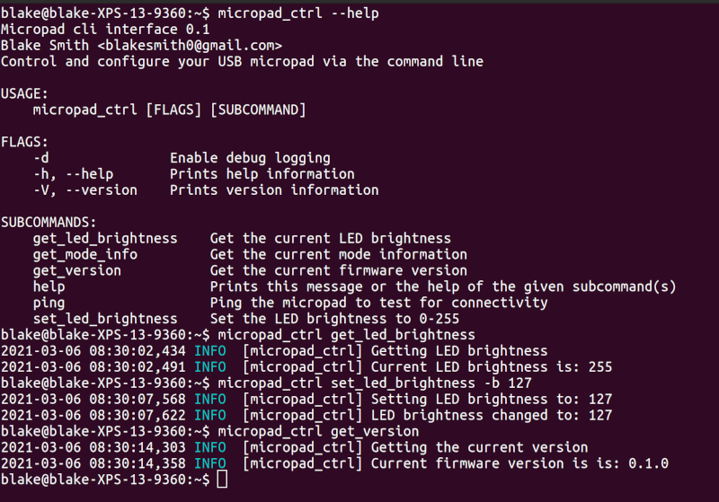
The result is a command-line client that can be used to control brightness, and other settings on the micropad itself. Right now, the messages it supports is pretty limited, but I have plans to expand this to support live changing the keyboard layout from the host computer.
What’s next
So far, I’ve done a first and second revision of the PCB and case. I’m waiting for a Prusa Mini+ 3D printer to arrive from backorder so I can iterate on the case design much more quickly, and without spending a bunch of money on externally printed parts. There is some other top plate buckling issues I plan to fix as well.
I also had to use a lot of unsafe Rust. This comes with the territory of embedded firmware, but I’d like to try some different idioms that give more safety guarantees. RTIC might be able to help, but I’m not sure if I want a ‘framework’ like this in the project. We’ll see.
In the meantime, check out the full source code, along with the Bill of Materials on Github!