The server rack continues to expand! In an effort to buy
hardware before the AI bubble continues to drive up computer hardware prices, I’ve added three more Minisforum UM690L
mini PCs to the basement rack (this time in black!).
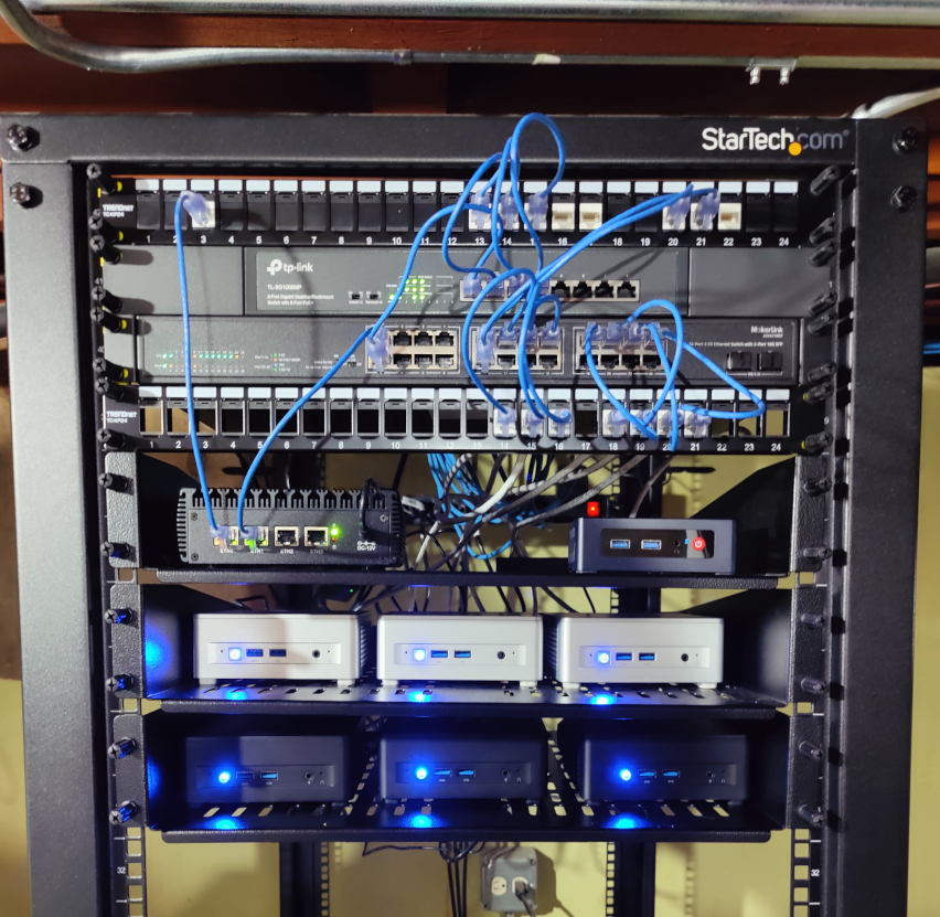
I’ll be using this new batch of machines to separate a testing cluster from “production” infrastructure
that runs the stuff in the house (Home Assistant, Jellyfin, etc.)
I haven’t yet isolated the network switching / routing, but that’ll come at some point.
In the meantime, I’ll keep on cheering for the AI bubble to crash in hopes of computer hardware
returning back to earth.
One thing that’s still underrated in programming: Skipping a library dependency and
coding something small that you need directly. No over-generalized library, no unecessary abstractions, no library dependency hell – just
straight forward code that solves your specific problem in the most direct way possible.
To put a longer story on it: I’ve been working on provisioning VMs with cloud-init NoCloud for
the cloud orchestration platform I’m building. To bootstrap VM state from a fresh image, I need to expose a VFAT disk from the host hypervisor
to the guest with the VM’s metadata (Network setup, hostname, users, etc.). The disk image needs to be dynamically built during
VM provisioning time, and injected with the correct instance information inside the VFAT volume for the guest to read.
VM provisioning happens in Rust code, so there are so a few different ways I considered implementing this:
- Build up a directory on a local scratch temp dir with the instance metadata files, and shell out to
mkfs.vfat with something like std::process to turn the directory into a vfat volume.
- Use an existing Rust library like fatfs to write the instance metadata files into a new FAT filesystem
Both of these require taking on external program or library dependencies.
I went a different way instead. I made a single zero-dependency Rust function that builds up the FAT filesystem in memory, and writes out the bytes directly to a file on the host.
It’s a few hundred lines of code, most of which are comments and tests. I read an old Microsoft FAT specification, wrestled with the hackish oddities of Long Filename support, and got
something working in a few hours time.
What’s missing from this implementation? So much!
- Only supports a fixed number of FAT filesystem clusters
- Only supports fixed filesystem sector sizes
- Only supports a hard-coded root directory size
- Hardcoded filesystem label only (It has to be the string
cidata to work with cloud-init anyways!)
- No read support
- Basic FAT12 only (No larger files with FAT32)
- No general file write interface: Just supports writing the 4 metadata files we need and that’s it
- Immutable writes only, no updates / mutations.
But this is all I need (and will probably ever need!). If I ever start doing anything fancier and dynamic with FAT filesystems, I can re-evaluate.
Instead, I get no breaking API changes from upstream libraries, no CVEs to patch, no license changes or rug-pulls, and code that’s straight forward and easy to fix and debug directly. Why carry around the extra weight of more dependencies for such a tightly scoped problem? We’re only writing 4 small metadata files to the vfat disk image after all.
Was this the quickest way to solve the problem? Probably not! Slapping in another dependency via cargo add and gluing some more APIs together would have probably gotten the problem “out of the way” faster from the start. But the initial expediency shouldn’t overshadow the benefits of building something tidy, compact, and definitionally simple like this.
I want less duct tape and glue in my programs. I want less moving pieces and maintenance. I want code that’s mine. I want systems that are load bearing and ready for production. I want more functionality, with less dependency.
If you’re looking for a Rust based Vmm alternative to Firecracker,
I’d check out Cloud Hypervisor. Cloud Hypervisor ended up hitting that sweet spot for me
in many places where Firecracker is chasing different outcomes.
Both projects share so many things to love:
- Entirely Rust based, sharing many quality crates from the rust-vmm project.
- Built on top of the Linux KVM hypervisor
- Good virtio device support (disks, network interfaces, etc.)
- Simple Vmm Http API
In contrast to Firecracker, Cloud Hypervisor directly targets long-lived, stateful VMs (but can also slim down to ‘microvm’ territory),
and thus supports other features that Firecracker will most likely never add.
UEFI boot support
Unlike Firecracker, which only supports direct Linux boot, Cloud Hypervisor can boot a minimal UEFI firmware. This
gives your guest VM direct control of the kernel upgrade lifecycle from within the guest. It also allows running OS types other
than Linux. If you’re running long-lived stateful VMs that expect to manage their own kernel version upgrades over
time, then this is what you want. I’m no fan of the complexities of UEFI, but the realities are that if you want wide-spread
guest boot support (including Windows, etc.), having at least basic UEFI support is a good and useful thing.
Firecracker requires using Linux Direct Boot. This limits your
guest VMs to Linux only, and requires that the Vmm itself manage the kernel upgrade lifecycle of the guest VMs. Firecracker is optimizing
for something different than Cloud Hypervisor: Lightweight, short-lived VMs that are biased towards serverless function workloads (It
was built for Amazon’s Lambda after all). Cloud Hypervisor also supports Linux direct boot in addition to UEFI support.
Qcow2 disk images
Firecracker only ships with Raw disk image support. The biggest drawback I hit with raw disk images is that it requires
pre-allocating the entire guest disk, consuming valuable host disk capacity (or implementing other complex setups like device-mapper for overlay).
These pre-allocations also lead to extra byte copying when shuffling block devices around a host cluster.
Instead, Cloud Hypervisor has direct Qcow2 support. This gives us baked in support for thin-allocated disk images (saving over-allocation), as well as backing-file
support. You can have read-only overlay semantics for shared disk image lineage, snapshots, etc. No external device
mapper required.
For generating base images, it’s much easier to generate Qcow2 images with base a base OS install, and then at VM provisioning time,
issue a quick metadata operation to the Qcow2 file to resize the image for each provisioned guest.
Beyond Qcow2 disk images, I previously wrote an experimental implementation of network attached block devices for Firecracker.
While this quick and dirty experiment worked, Firecracker’s focus on short-lived VMs for serverless functions made me doubt whether network-attached storage code patches would be welcome upstream. I’d
love to push contributions back to Cloud Hypervisor that enable arbitrary block-device backend support.
Live migration
I haven’t gotten to plumb in live-migration yet, but this is something Firecracker is also unlikely to ever add, due to
its focus on short-lived VMs. I’m looking forward to implementing this one on my cluster control plane!
Not Amazon
Fundamentally, I’m just not comfortable making deep investments in a project that’s governed by Amazon. Amazon’s values don’t align well
with mine as of late, and I’d rather invest in tooling that doesn’t put more compute power in Jeff Bezos’ pocket.
To be sure: there are other hyperscalers involved in Cloud Hypervisor, but the diversity gives me more confidence. The last major release saw contributions
from technologists at Microsoft, Google, Meta, IBM, Tencent, and several more.
I’m much choosier about licenses and governance of open source projects I contribute to these days. Too many rug-pulls for comfort.
Give it a try
I was able to add Cloud Hypervisor support to my internal cloud control plane in about a day or so. It shares many of the broad
feature sets that Firecracker has, and then goes further.
If you’ve ever been intrigued by Firecracker, and are looking for an alternative whose mission isn’t so pigeon-holed into serverless, I’d
give Cloud Hypervisor a look!