This is a blog post in a series on converting a 1978 Puch Maxi Moped from fuel combustion, to electric powered.
Read Part 1 here. Read Part 2 here. Read Part 3 here. Read Part 4 here. Read Part 5 here.
Motor Plate Progress
I’ve been continuing to iterate on the motor plate frame fitting. A few new tactics to share:
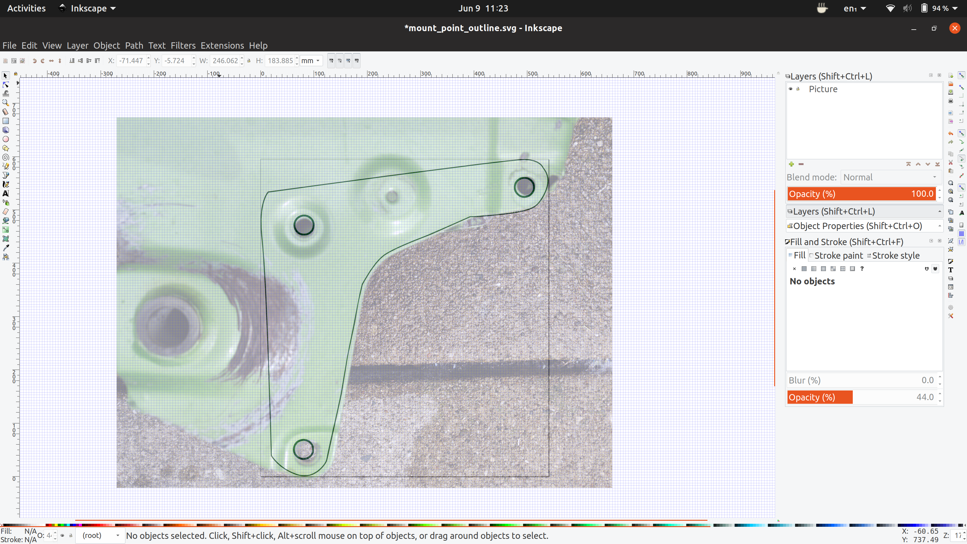
My brother in law gave me a really helpful tip: Take a picture of the frame, and then size the image to a known sized reference point on the frame. In this case, I knew that the motor mount holes are 9mm in diameter, so I scaled the image in inkscape until the mount holes looked close to their actual size.
From there, I traced the mount holes and the contour of the frame outline. Inkscape can export DXF files, which I imported into OpenSCAD as a useful design reference.
This helped me get the holes “in the ballpark” of the mount points.
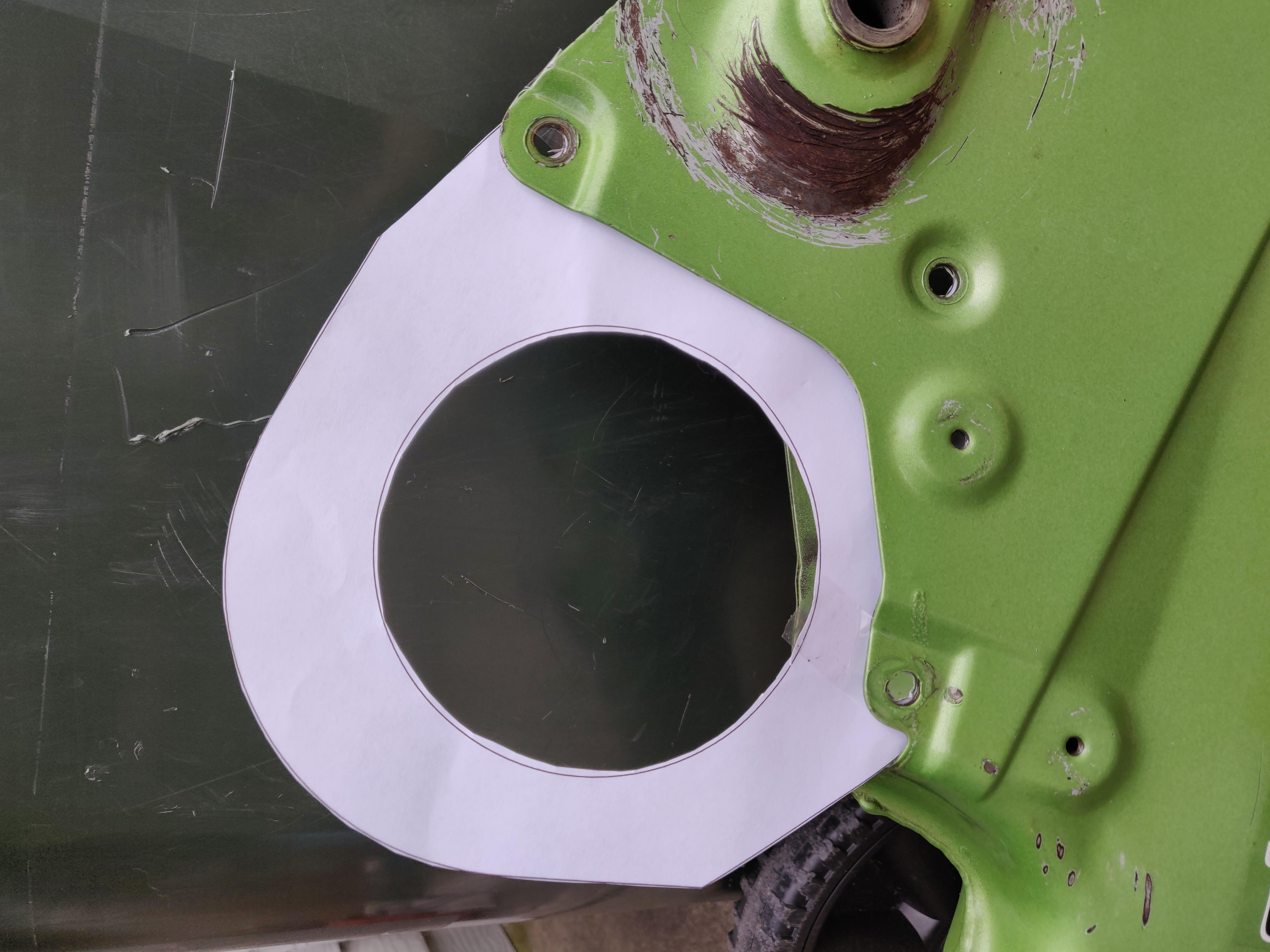
My next tactical change was to iterate using a paper cutout of the plate, rather than going through a lot of lengthy 3D prints.
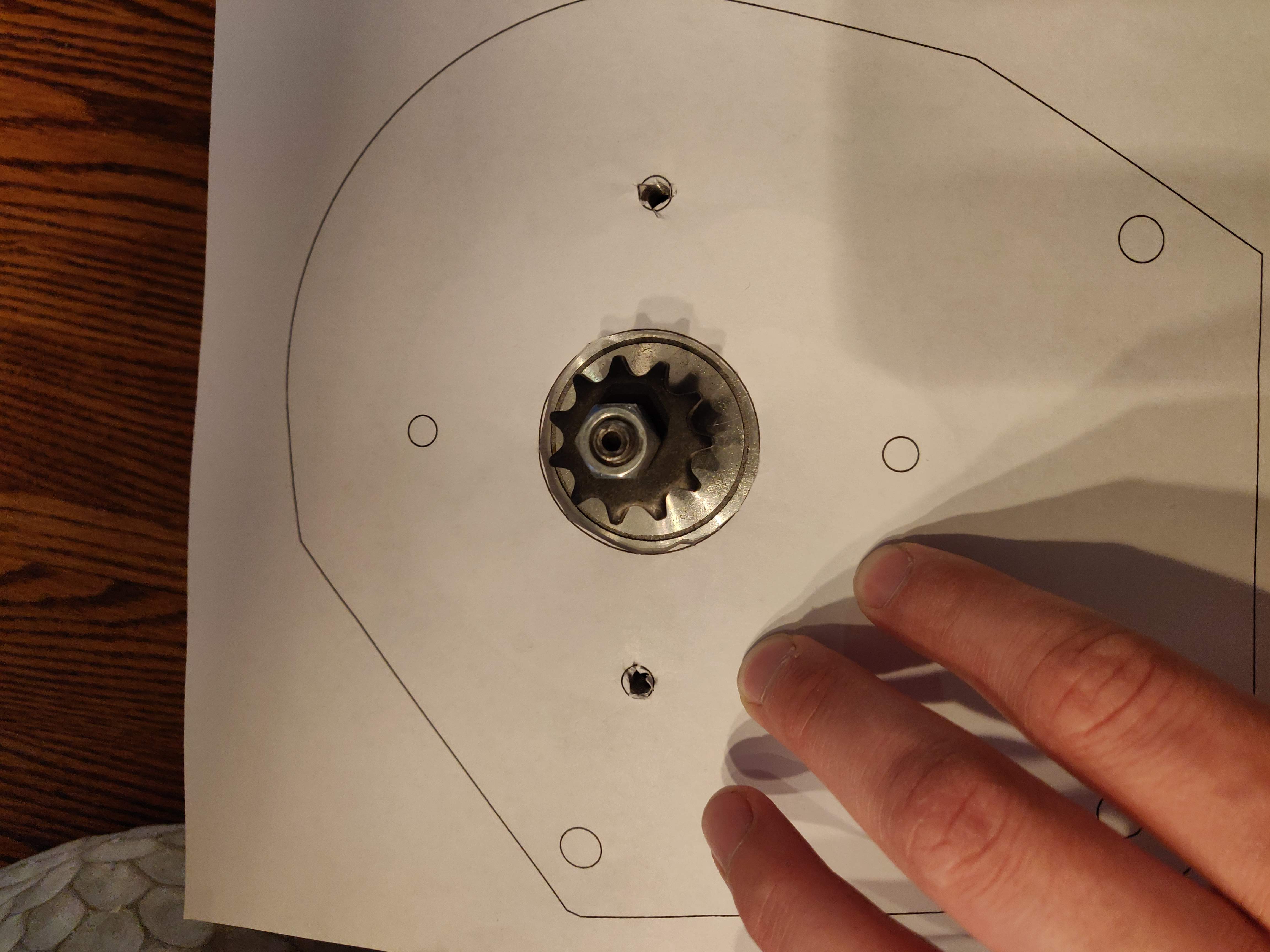
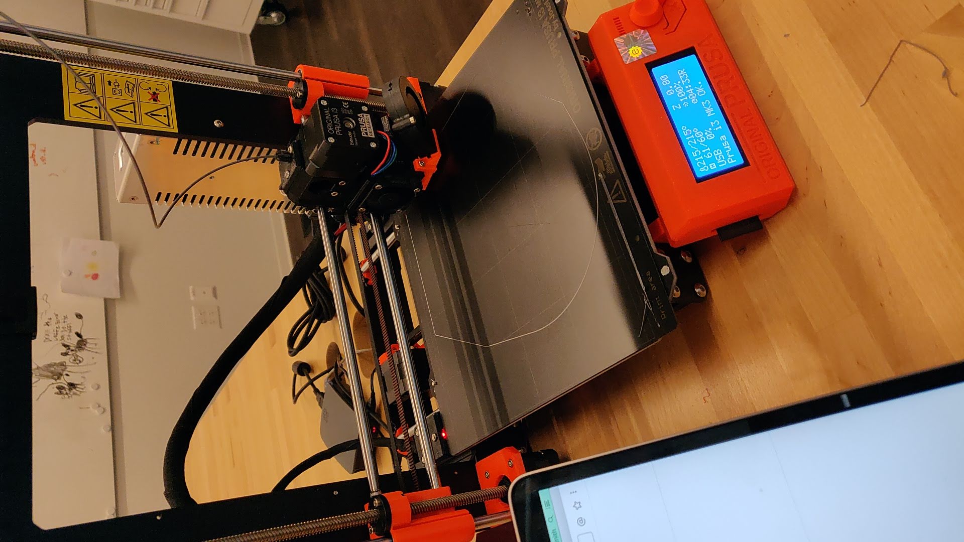
This allowed me to churn through 5-6 rapid iterations, and make lots of small tweaks and adjustments. 15 minute iterations, instead of 4 hour iterations makes a big difference when you’re reverse engineering dimensions. Paper printout iterations are also much cheaper in material cost. After getting close with paper, it’s back to the 3D printer for a few more alignment changes.
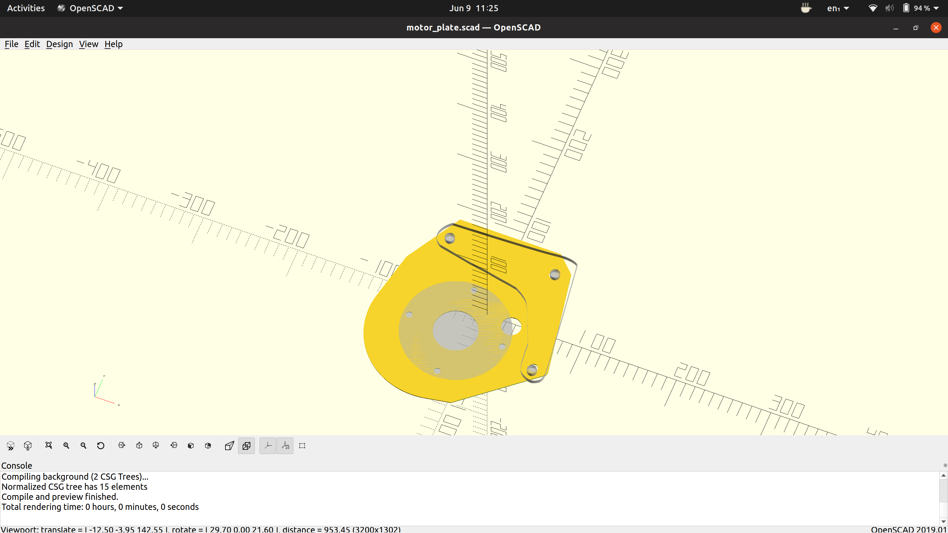
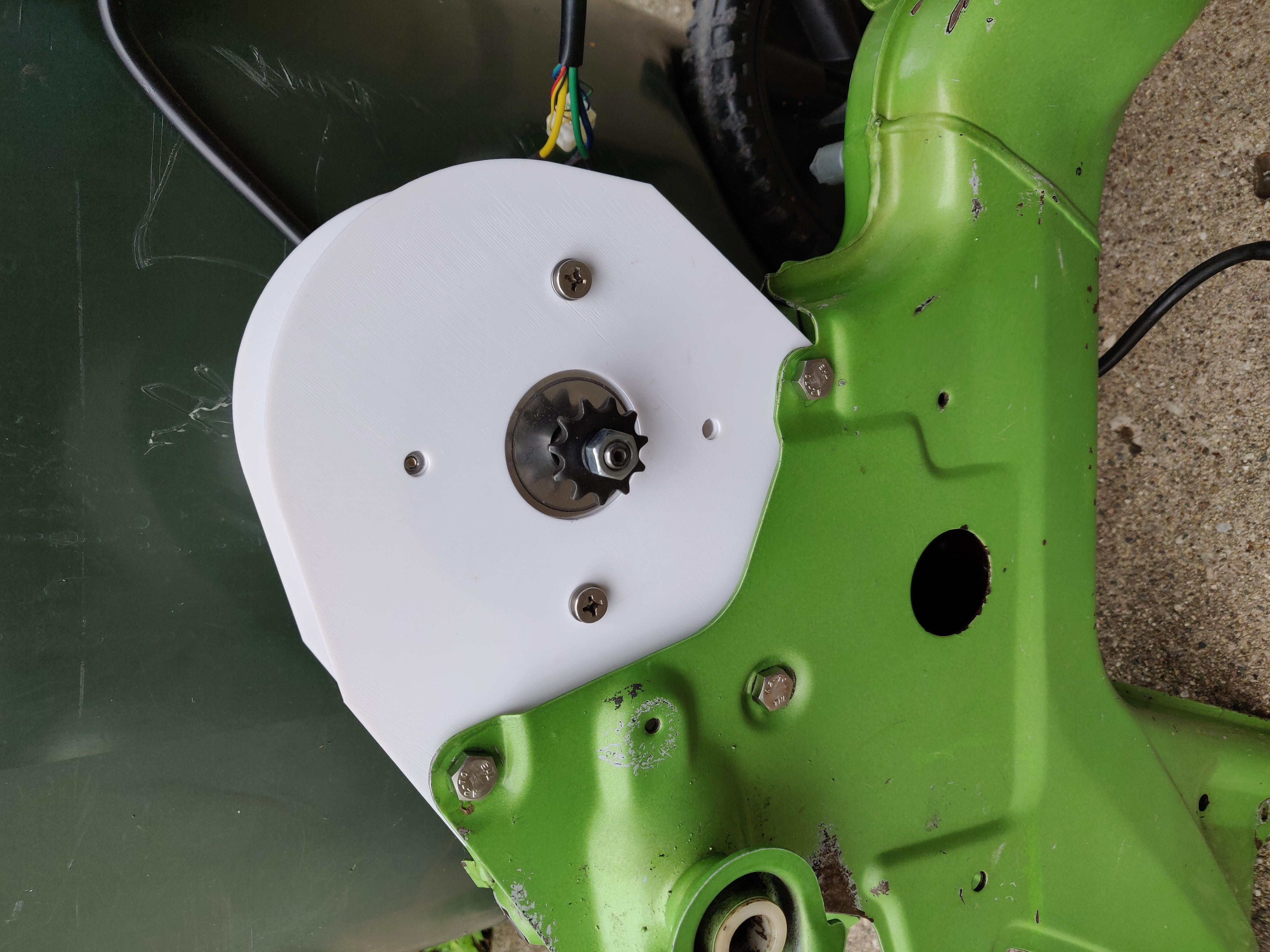
After 4 iterations with a 3D printed prototype motor plate, everything was starting to line up. Most of these plate design iterations were small hole alignment adjustments and tolerance tweaks. I used a new service called OshCut to have the designs laser cut out of stainless steel. Within 2 weeks of uploading my DXF files, the stainless steel parts arrived in the mail. I love the era we live in; access to this kind of service 20 years ago would have been unthinkable.
Here’s the progression from design to finished, painted motor plate.
CAD Design using OpenSCAD.

First wildly inaccurate 3D print.

Switching to paper cutouts, for faster iterations.
3D print iterations, for minor tweaks and adjustments.
Stainless steel plates, raw from OshCut

Final, painted stainless steel plates, matching the new paint job (more info on painting below).

Up until this point, the motor plate design has been my favorite sub-problem of the entire project. It combines my love for computer design, with the satisfaction of seeing the work reified into the “real world”, with all the problems and challenges therein.
If you’re interested, the OpenSCAD source code for the design is up right here.
Paint Job
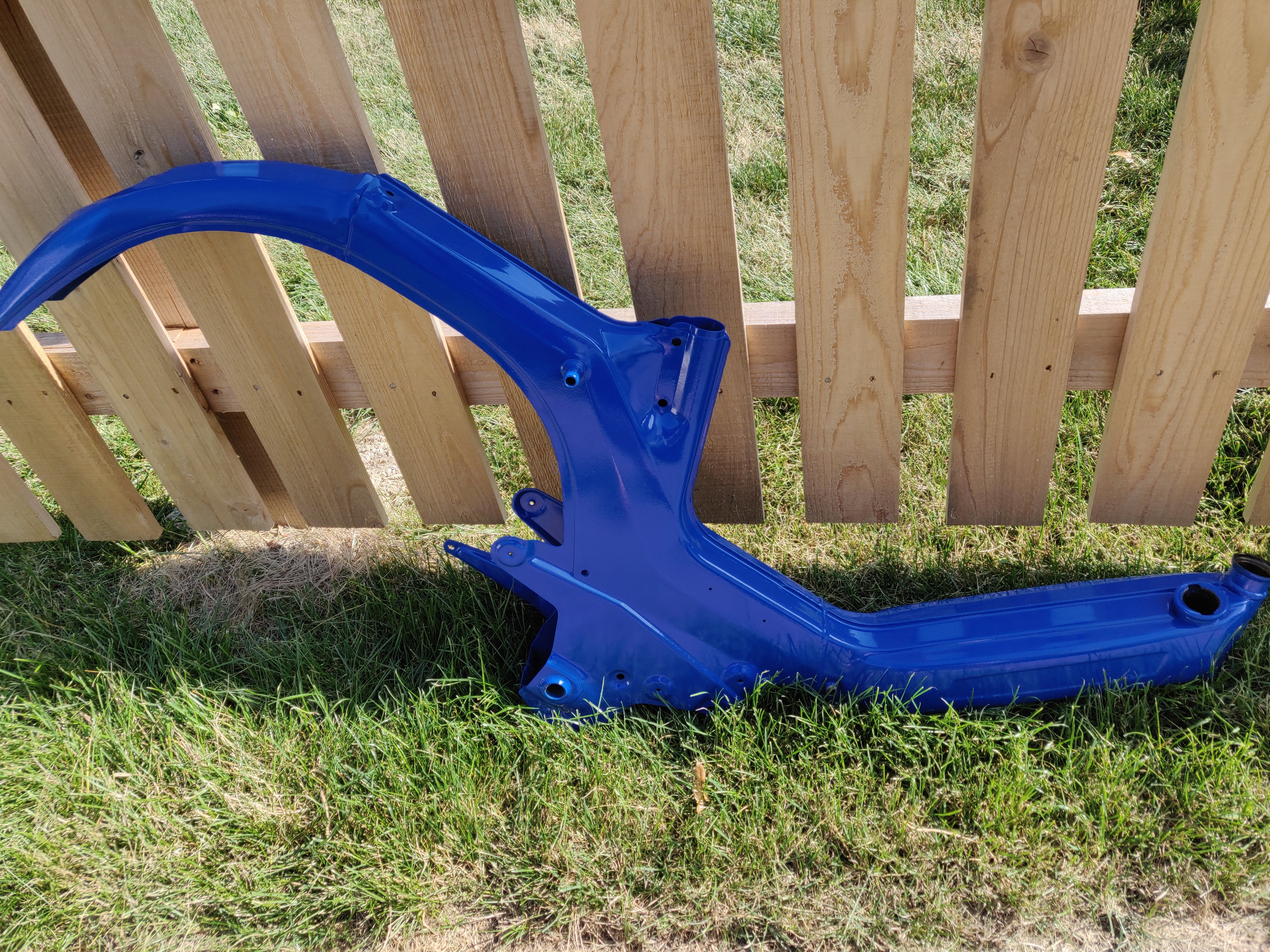
For a moped manufactured in 1978, the paint job was surprisingly not that bad. There were some deep gouges in a few place, and general surface scratches. However, I knew I wanted something that looked all clean and brand new. That meant either spray painting it myself (cheap, but lower quality and more time invested), or getting someone to help powder coat the frame and components. A few years back, I helped my dad restore an old Schwinn Varsity road bike, and we found a powder coater nearby who did fantastic work. If you’re on the northwest side of Chicago, I highly recommend giving Bob a call at Precision Powder Coating.
Bob was able to give me a rough quote for painting the frame via pictures exchanged over email, and I drove the frame and parts over to his workshop. Side note: If you’re dropping off something that at one point had gasoline or other combustibles in it, make sure you clean those areas thoroughly! Powder coating involves putting your parts in a really hot oven, and you don’t want any explosions to happen in the paint process. Bob was patient with me while I cleaned and de-fumed the gas tank for safe paint application. Since I don’t plan on using the gas tank anymore, I soaked the tank with Dawn for several days, draining and re-soaking multiple times.
Three weeks at the powder coater, and it was time to pick her up.
My son approved of the paint job.

She looks brand new!
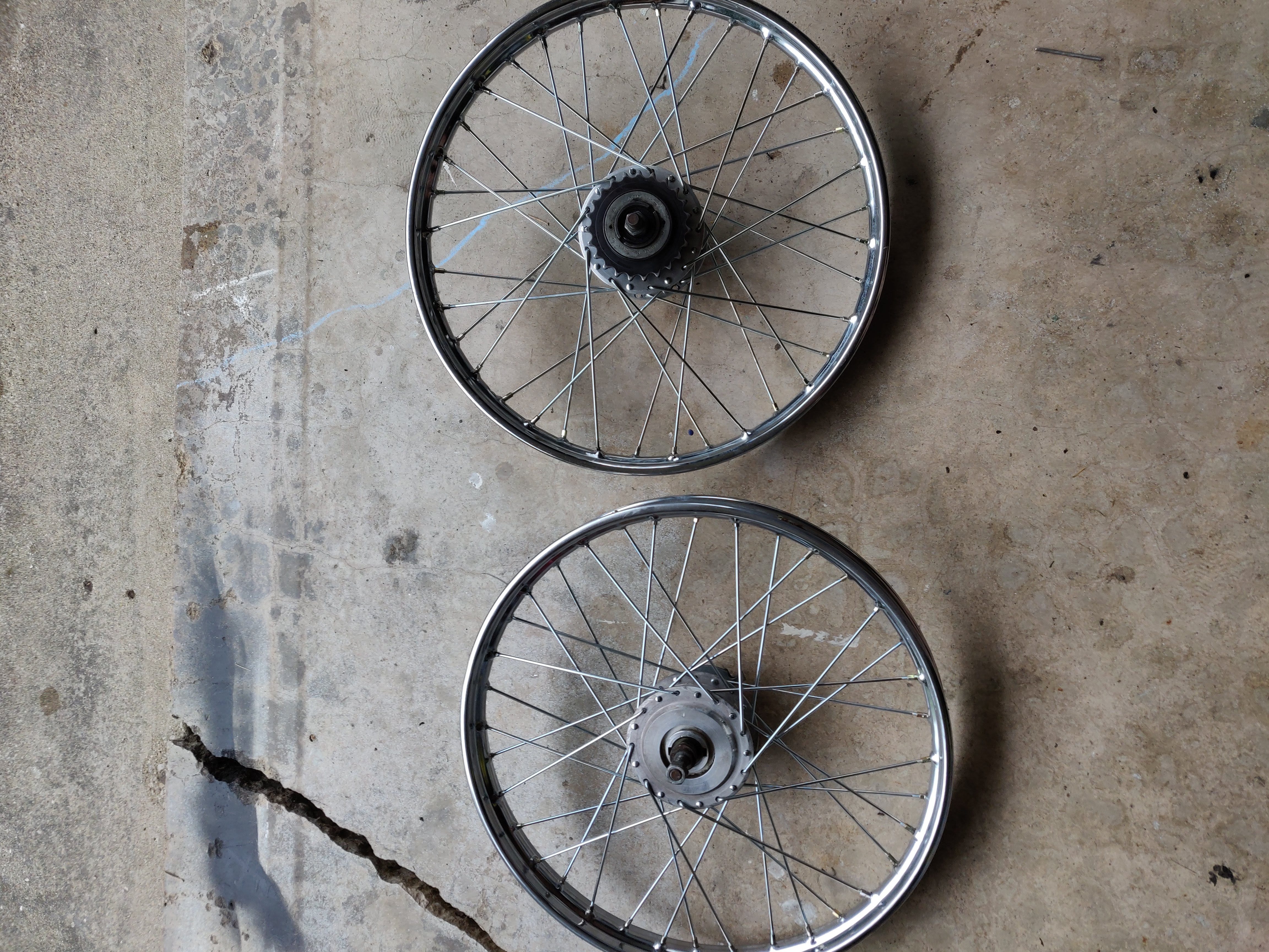
Detour: Wheel build
I spent some time cleaning the wheels that came with the bike, and in the process discovered the rear wheel had 6 broken spokes that I originally missed during the purchase, as well as a dented rim. The front wheel was in OK shape, but ended up having a bent axel as well.
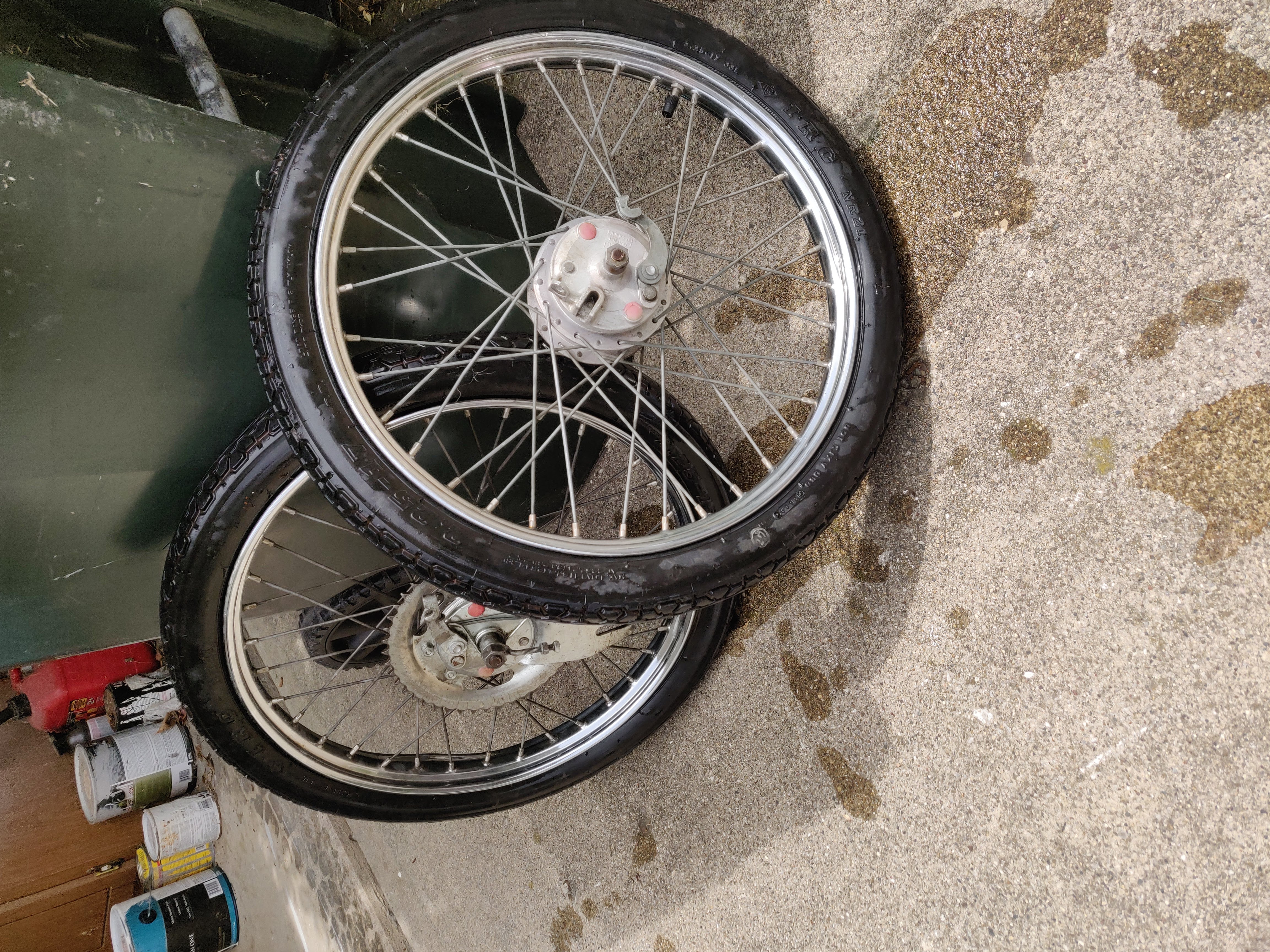
Rebuilding wheels was definitely not part of the original plan, but that’s just how these kinds of projects go. It’s 10x more fun if you roll with the punches, and learn some new things along the way. I hopped on treatland, made the plunge, and bought new rims and spokes to rebuild both wheels with the existing hubs. I had never laced spoked wheels before, so this required some more youtube spelunking for videos to walk through the process. I focused on motorcycle wheel lacing videos, since that most closely matches moped wheel work.
Lacing both wheels loose probably took me 4-5 solid hours. I would get 80% of the way through a wheel, and then find that there’s 1 or 2 spokes that I can’t pivot into position with the other spokes in the way. Lots of trial and error, and sweating to go with it (lacing wheels when it’s 95F outside makes it extra challenging!).
At this point, I had the wheels in the correct star pattern, but were with no spoke tension at all. Next up was learning how to balance the wheels for even rotation. It took me awhile to wrap my head around the basic tactics for wheel balancing, but once you grasp the mechanics, it’s not too bad. Patience is key with wheel balancing: Small adjustments are your friend.
My son loves to “help daddy work on his new bike”

Because the wheels had spent so many years absorbing the grime from the streets of Chicago, I also wanted to repack the axel bearings. This turned out to be easier than I originally anticpated: Unthreaded the cone nuts, cleaned out races inside the wheel and soaked the bearings in carb cleaner, applied grease and reseated the bearings in the wheel.
Now they spin like they’re brand new!
What should have been the easiest part of the wheel rebuild process ended up being the most frustrating: I popped 5 tubes trying to get the rear wheel tire back on. My experience is with changing bicycle tires, which have much smaller, plastic tire irons to lever the wheel over the bead of the rim. Using metal tire spoons and cranking too hard turns out to be a recipe for lots of tubes with holes in them.
I had much more luck when I applied some simple lubricating spray cleaner around the tube, which helped keep the tube and tire loose when getting it onto the wheel.
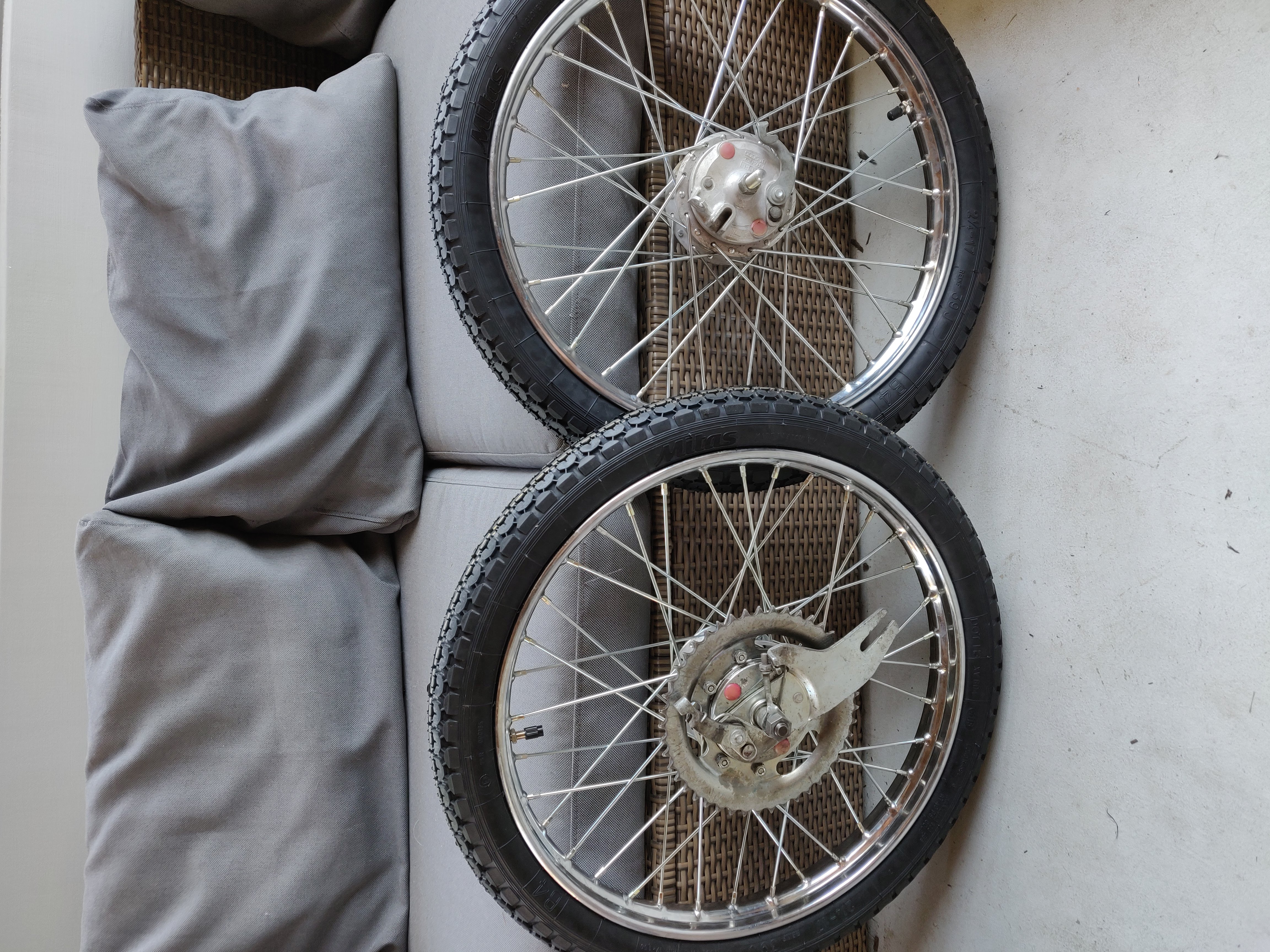
Finally, all put together!
Starting Reassembly
Now that all the components are:
- Cleaned.
- Repainted.
- Rebuilt (wheels)
It’s time to start reassembly! Here she is, starting to come together:

In the next post, I’ll continue with reassembly, and hopefully get into some chain sizing, initial motor testing, and other final touches. Stay tuned, she’ll be up and running soon!
Next: Read Part 3 here