This is a blog post in a series on converting a 1978 Puch Maxi Moped from fuel combustion, to electric powered.
Read Part 1 here. Read Part 2 here. Read Part 3 here. Read Part 4 here. Read Part 5 here.
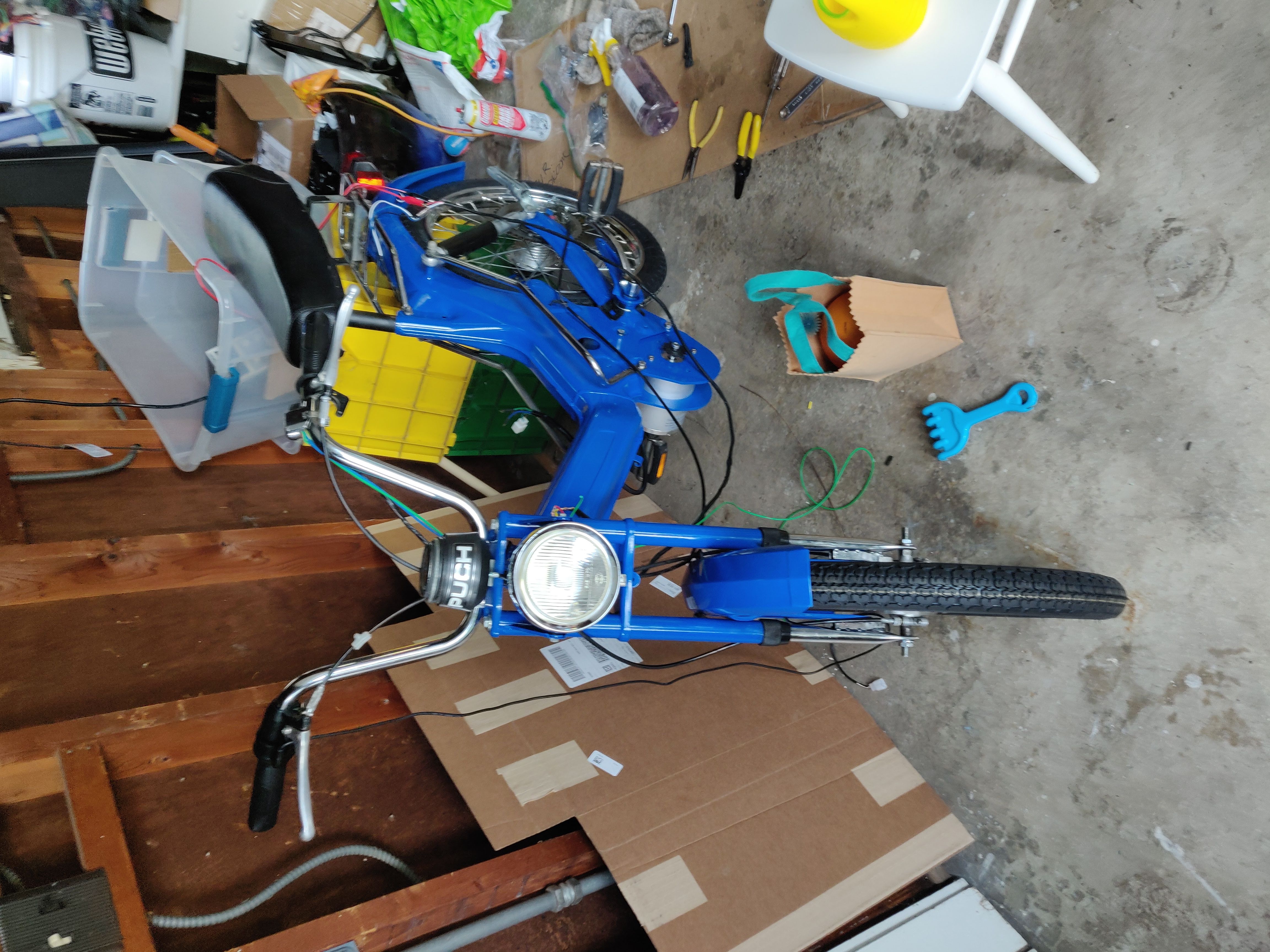
They say that 80% of the work comes in the last 20% of a project. That’s the current mode that my Puch Maxi electric conversion project is in. After getting a lot of the frame put back together, I’ve come down to a lot of the necessary detail work that’s required to get the thing moving.
12 Volt Electrical
Since I selected a motor and controller that operates at 48v, I knew I’d probably need to have a different voltage system to power the other peripherals on the bike:
- Front headlight.
- Rear brake light.
- Horn.
The common voltage standard on most motorcycle and automotive systems is 12v DC, and so I decided to go with that. This has the benefit of making parts easier to source, and components easier to find. 12v DC is in contrast to the 6v AC electrical system that’s present on a stock Puch Maxi. Compared to the sometimes strange wiring scheme of a stock Maxi, the wiring for the conversion is quite straight forward.
I took apart the stock headlight and brake lights on my Maxi, measured the diameters of the light bulb sockets, and found some modern, 12v replacement 1157 sized LED bulbs that matched the dimensions!
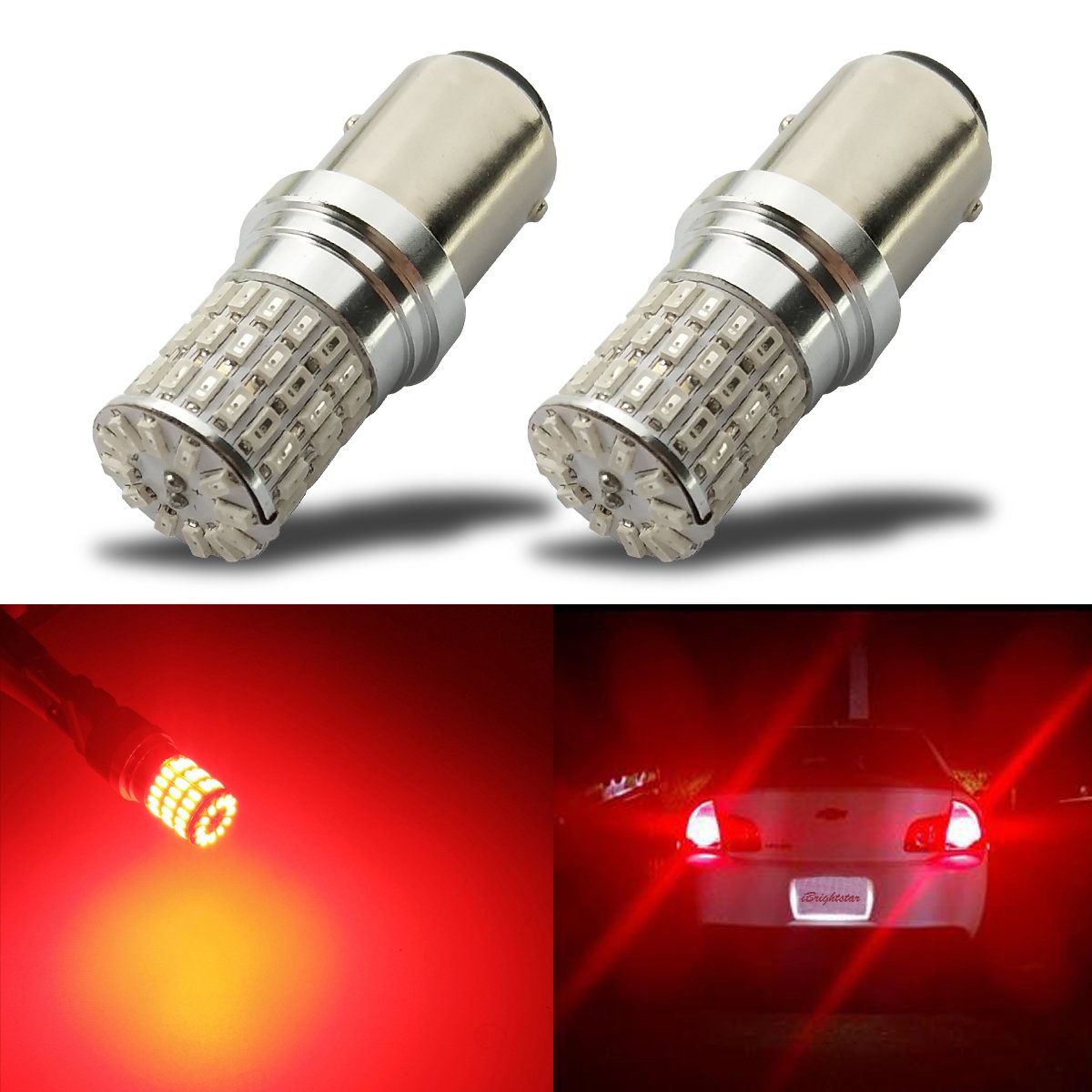
The locking tabs on the sides of the bulbs didn’t go in perfectly at first, but with a little bit of plastic reshaping, I was able to make them fit great.
The headlight uses the same style light, but in white instead of red. A word of warning: Use red tail bulbs, even if your light has a red cover over it, otherwise your light ends up looking more pink than red!
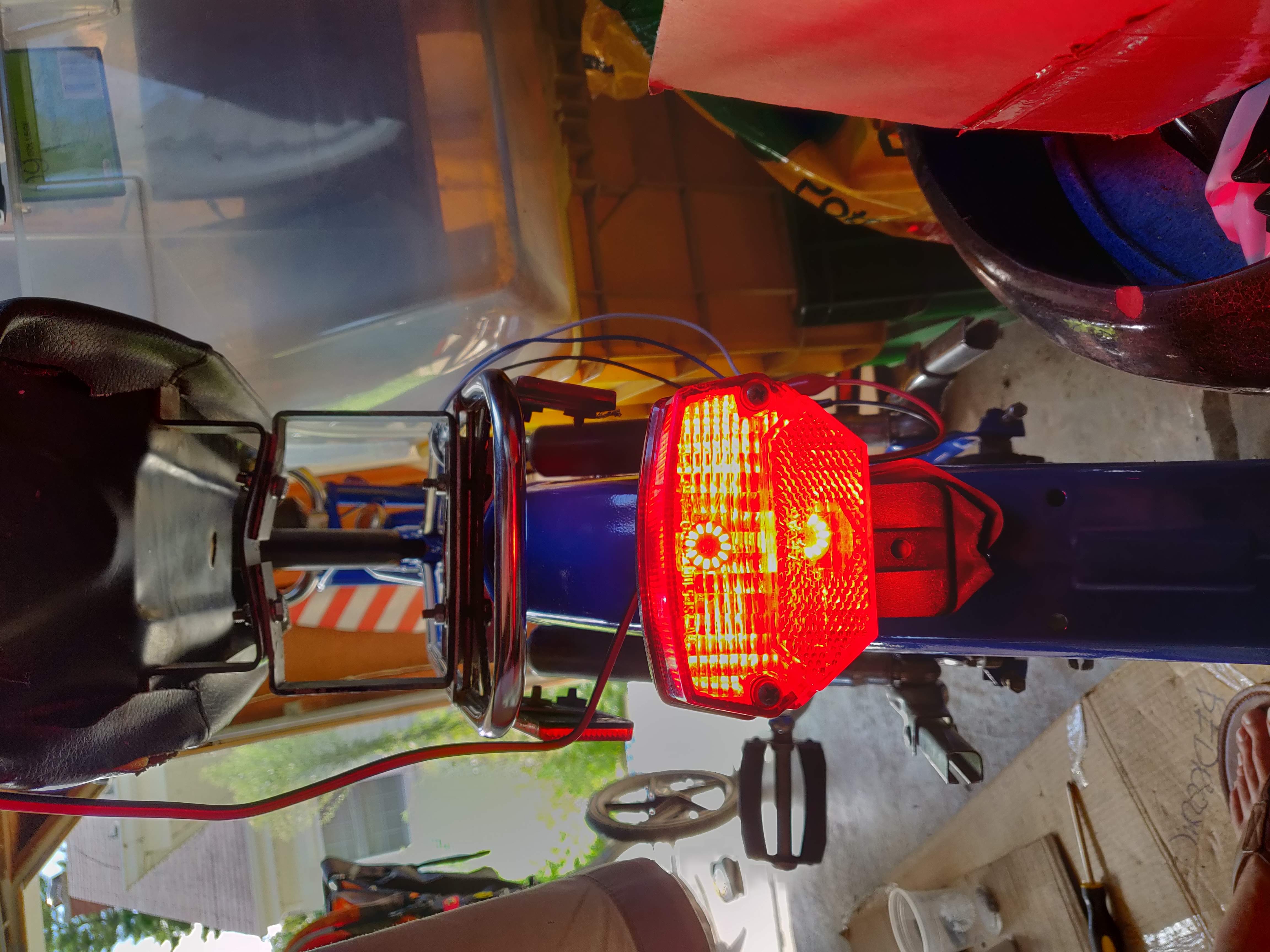
The tail light has two LEDs: One that turns on when I turn the main headlight on, and one that’s wired into the brake switch that activates when the brake lever is squeezed.
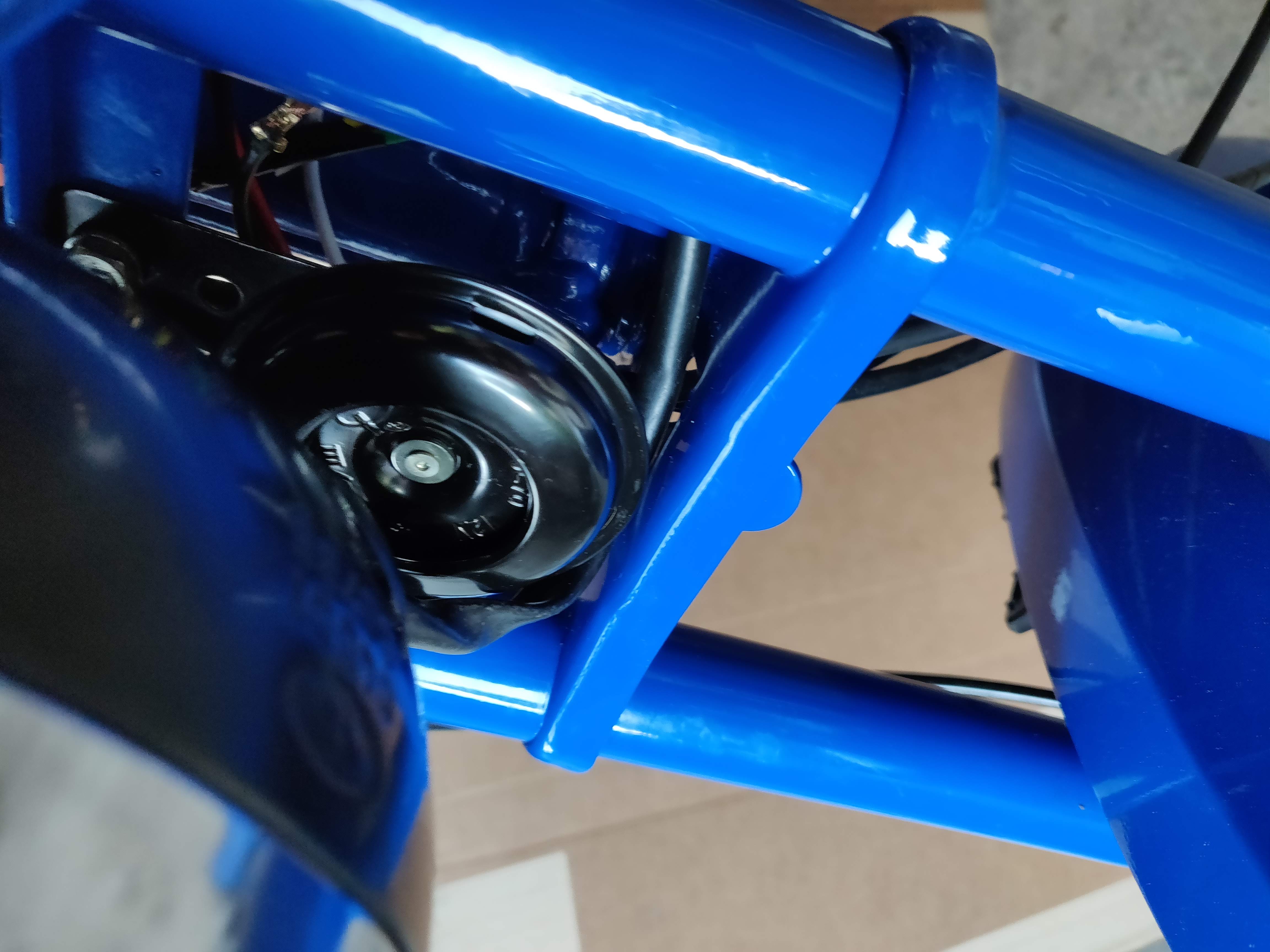
I also opted to purchase a new horn for the bike, since the existing one didn’t seem to work on DC current.
I used my bench-top power supply to verify that all the 12V components were working. All the wires are pretty nasty looking at the moment, I promise I’ll clean them up later!
Main Electrical
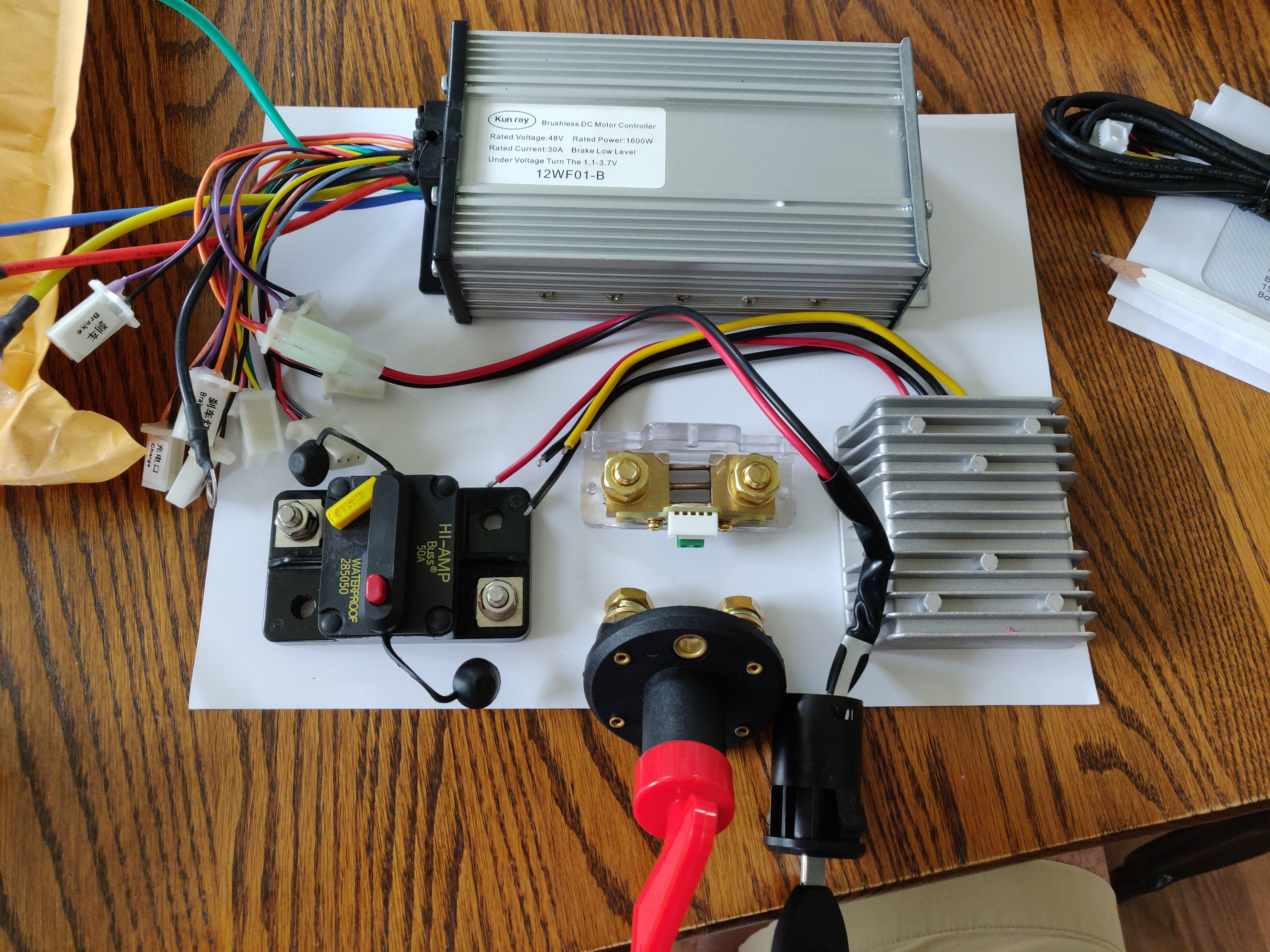
The 48v system has a few necessary pieces that need to be integrated into the system:
- A safety circuit breaker. Should there be any electrical failures, short-circuits, or current overruns, we want the system to shutoff for protection. This is the first item connected to the battery.
- A master disconnect switch. I wanted a way to disconnect all the electrical systems, especially with curious children who might play with the bike when it’s parked in the garage.
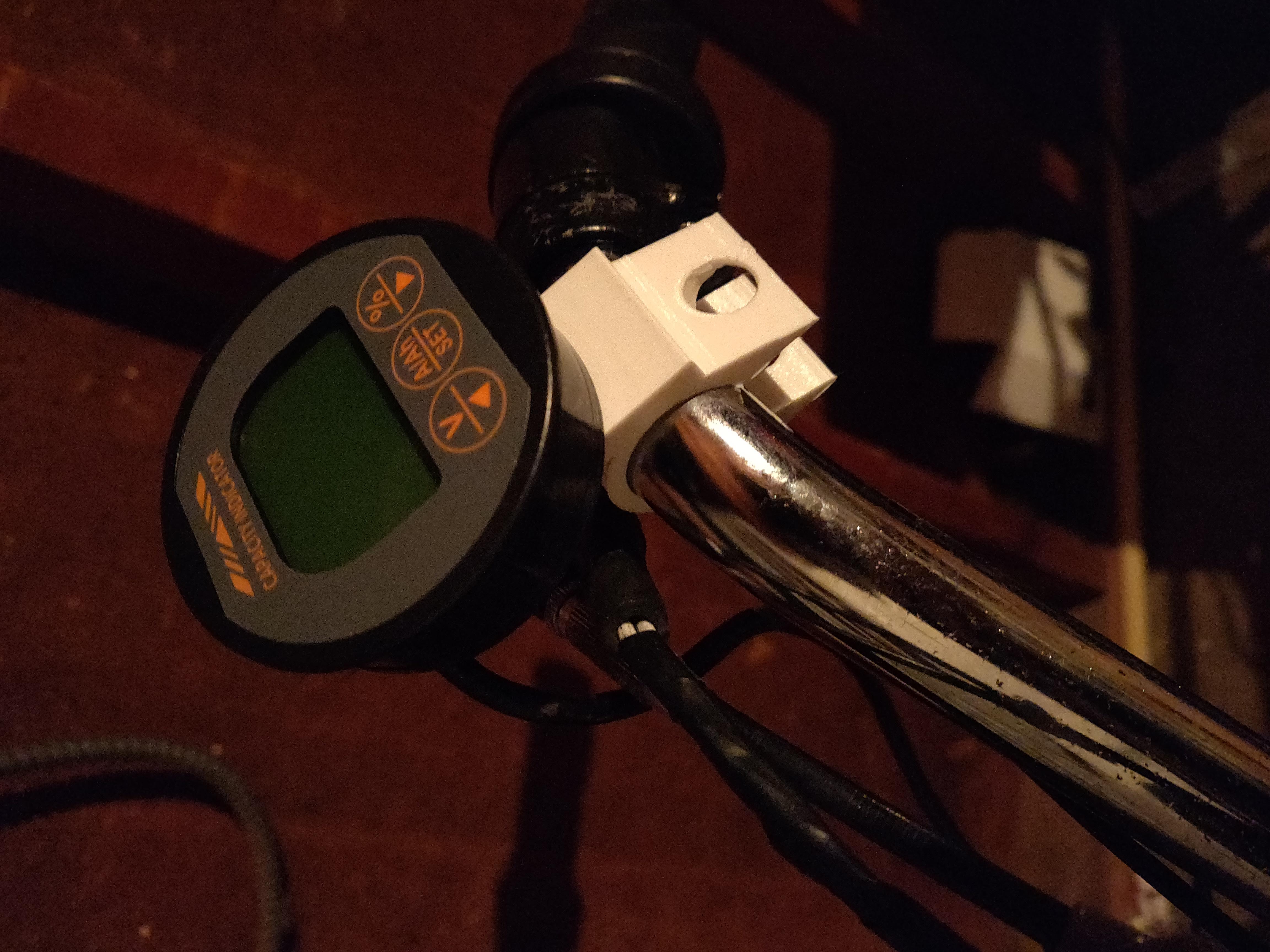
- A volt / amperage meter, with shunt. This can be used to measure voltage / amperage levels in the system, and can also provide a “capacity guage” to know charge level.
- A 48v to 12v DC-DC converter. Since the main battery runs at 48v, and the peripheral systems run on 12V, we need a way to step down the voltage to supply power to the lights and horn.
I laid out all these devices on a piece of paper (which would eventually become a board of wood), and wired them all together.
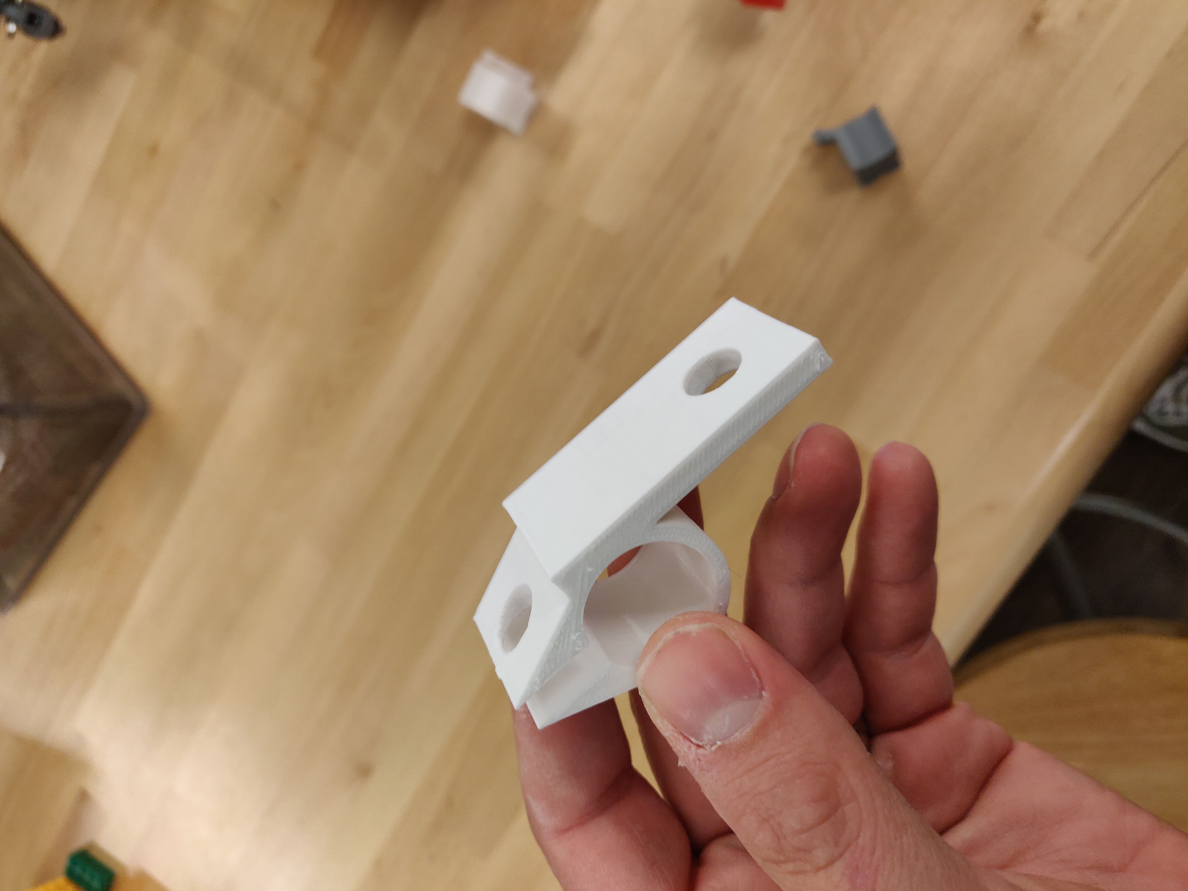
The volt / amperage meter display was designed for a panel mount arrangement, so I needed to 3D print a display holder that will mount on the handlebars (OpenSCAD code is here).

I also bought a really small outdoor circuit box that matched the sizes I need to fit these electrical components on the back luggage rack of the bike. I spray painted it black to blend in better with the rest of the bike’s color scheme.
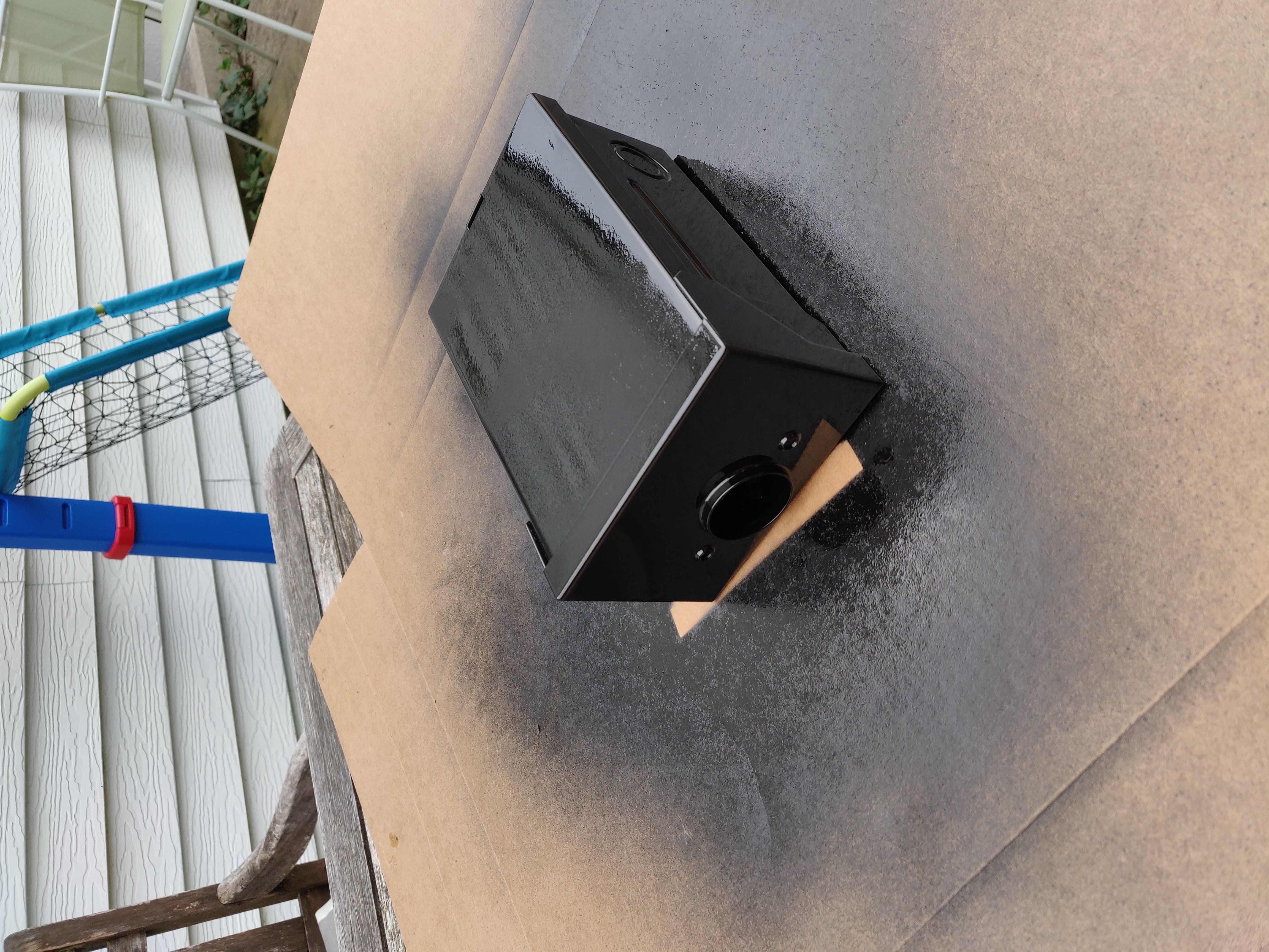
The eletrical box, while not being the prettiest thing, is a great solution:
- Because it’s meant for electrical, it already has the appropriate holes to route in and out of the box.
- It’s also easy to lock shut, for extra safety in case of snooping children.
Motor Shaft Problems
I encountered some other motor alignment issues, that I should have thought of earlier in the project (live and learn!). After getting the motor mounted into the frame, the motor shaft length on my motor was just a few centimeters shy of clearing the frame along the chain line:
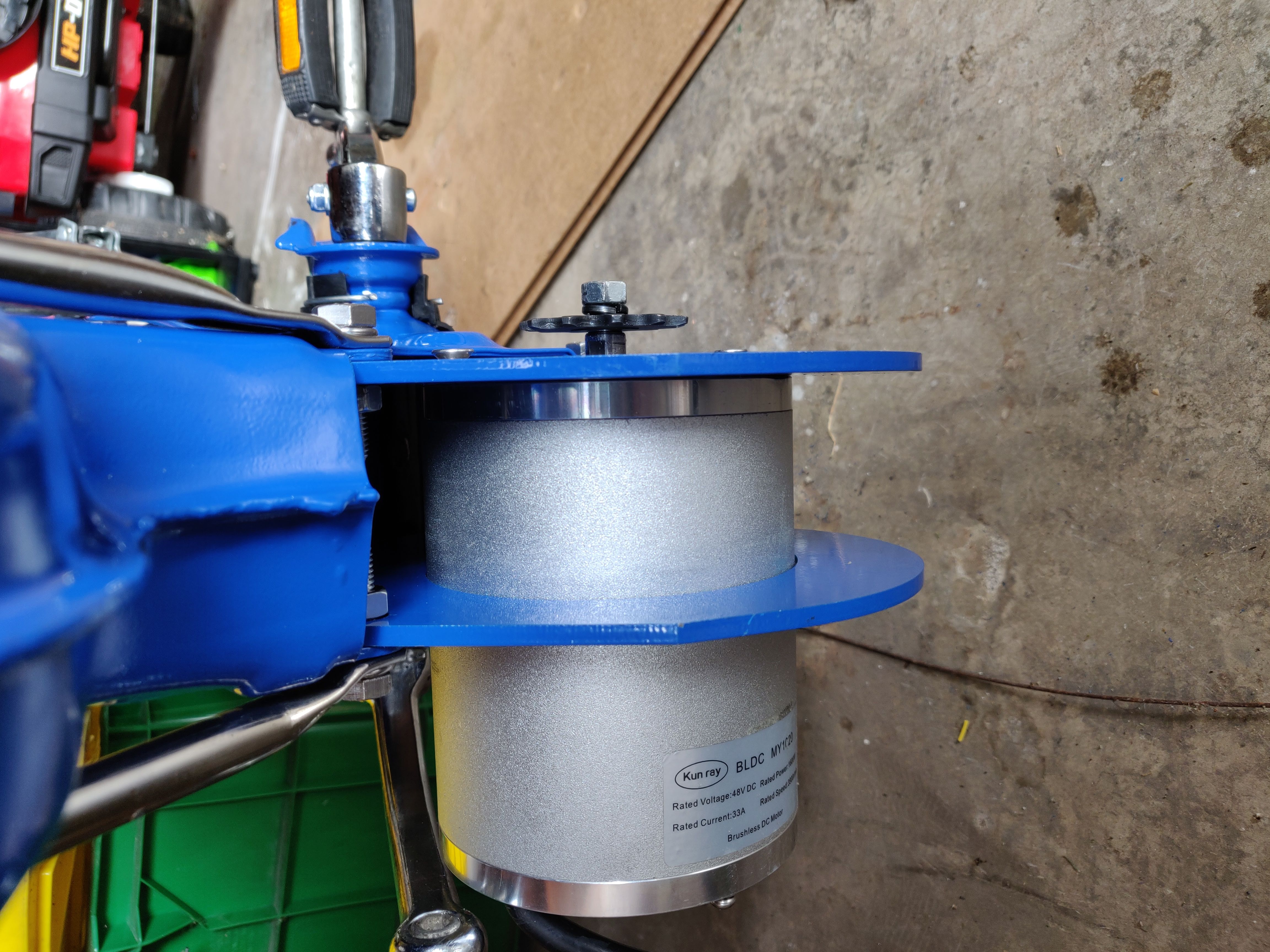
The result of which would be the chain rubbing up against the side of the frame, and not lining up nicely with the rear sprocket. This problem is further compounded by the fact that my motor doesn’t have a replaceable shaft, and uses a non-standard sprocket mounting scheme that’s not widley supported in the rest of the industry.
Learn from my mistake and choose a motor that either has a nice standard shaft size that’s easy to align to your needs or purchase adapters for, or pick a motor that can easily have its shaft swapped out for a different one.

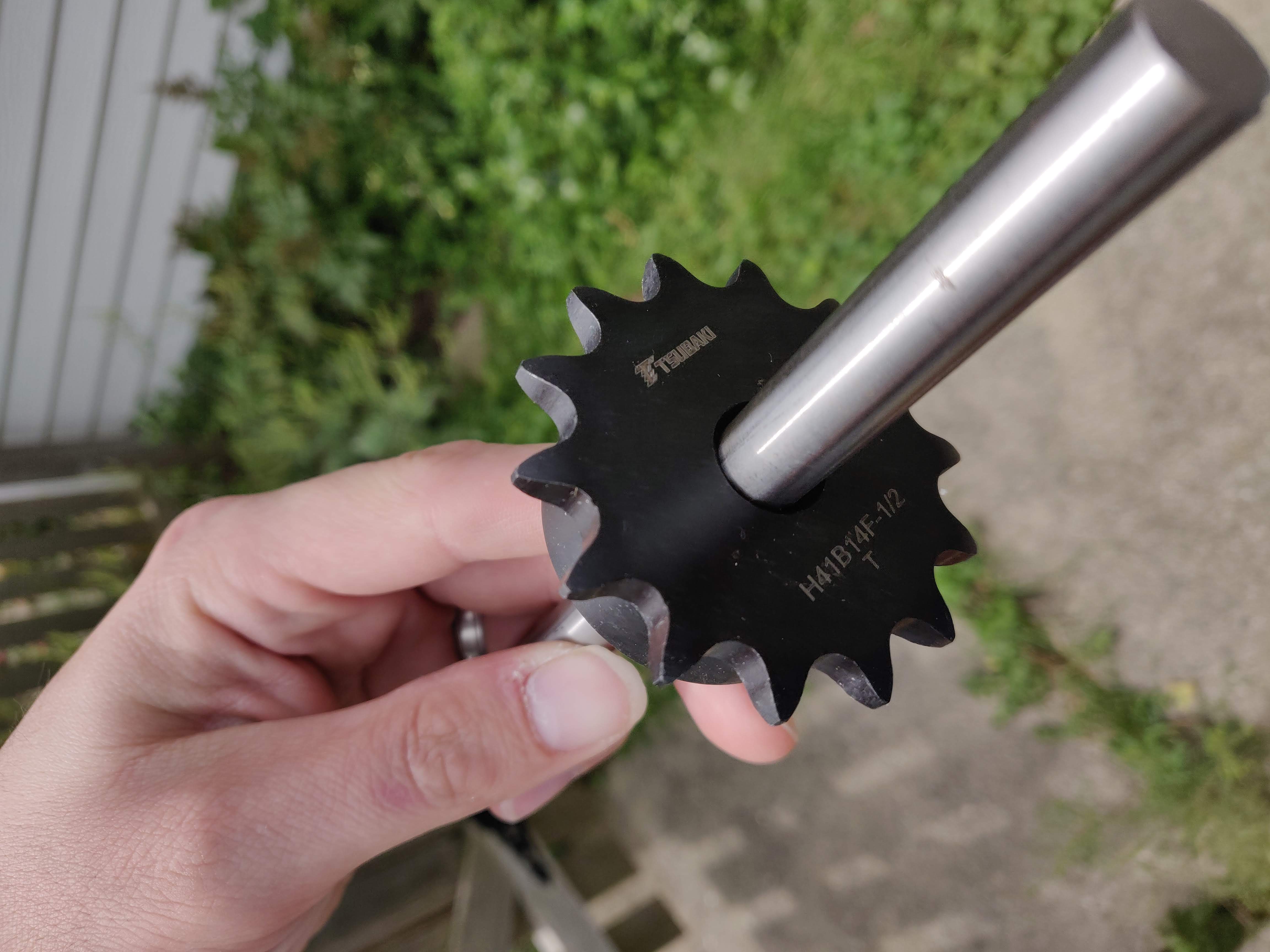
My initial plan to fix this was to purchase a new 1/2” keyed shaft, use a lathe or drill press to drill a hole into the shaft, and then thread the shaft with a left-handed tap onto the end of the existing shaft. This would allow me to extend the existing shaft, and at the same time, convert it to a standard shaft size that can take a plethora of different sprocket options that are available on the market.
Turns out the left handed thread would just unscrew the shaft extension due to the rotational torque of the motor.
My neighbor is helping to connect me with a machinist who has some ideas of how we can solve the problem. I’ll keep you posted on progress and updates.
Up Next
Progress has slowed down, due to the difficulty of the problems I’m working through. I’m hoping by my next post, I can have my shaft & chain alignment sorted out, and have the rest of the electrical system wired up. From there, I can size out my batteries, and get things rolling. Stay tuned!
Next: Read Part 4 here